Method of fabricating long-wavelength VCSEL and apparatus

a technology of vcsel and vcsel body, which is applied in the direction of lasers, semiconductor lasers, nanotechnology, etc., can solve the problems of poor thermal conductivity and insufficient active region of vcsel operation, and achieve good thermal conductivity, good mirror stack, and different refractive index

Inactive Publication Date: 2005-02-08
JDS UNIPHASE CORP
View PDF8 Cites 7 Cited by
  • Summary
  • Abstract
  • Description
  • Claims
  • Application Information

AI Technical Summary

Benefits of technology

[0014]In a preferred embodiment, an indium phosphide (InP) active region is grown on an InP based substrate and an AlAs / GaAs based metamorphic DBR mirror stack is epitaxially grown on the active region. AlAs / GaAs has good thermal conductivity and sufficiently different refractive indices to produce a good mirror stack. The supporting substrate may be either a mechanical InP based substrate bonded to the active region or a layer of plated metal, such as copper, silver, gold, nickel, aluminum, etc. The plated metal supporting substrate provides additional thermal conductivity for the VCSEL.

Problems solved by technology

When an InP based active region is used, however, the DBRs or mirror stacks lattice matched to the supporting substrate and the active region do not provide enough reflectivity for the VCSELs to operate because of the insignificant difference in the refractive indices between the two DBR constituents.
Dielectric mirror stacks can be used for VCSEL applications, but they suffer from poor thermal conductivity.

Method used


Image

  • Method of fabricating long-wavelength VCSEL and apparatus
  • Method of fabricating long-wavelength VCSEL and apparatus
  • Method of fabricating long-wavelength VCSEL and apparatus

Examples


Embodiment Construction

y for the VCSEL.

BRIEF DESCRIPTION OF THE DRAWINGS

[0015]Referring to the drawings:

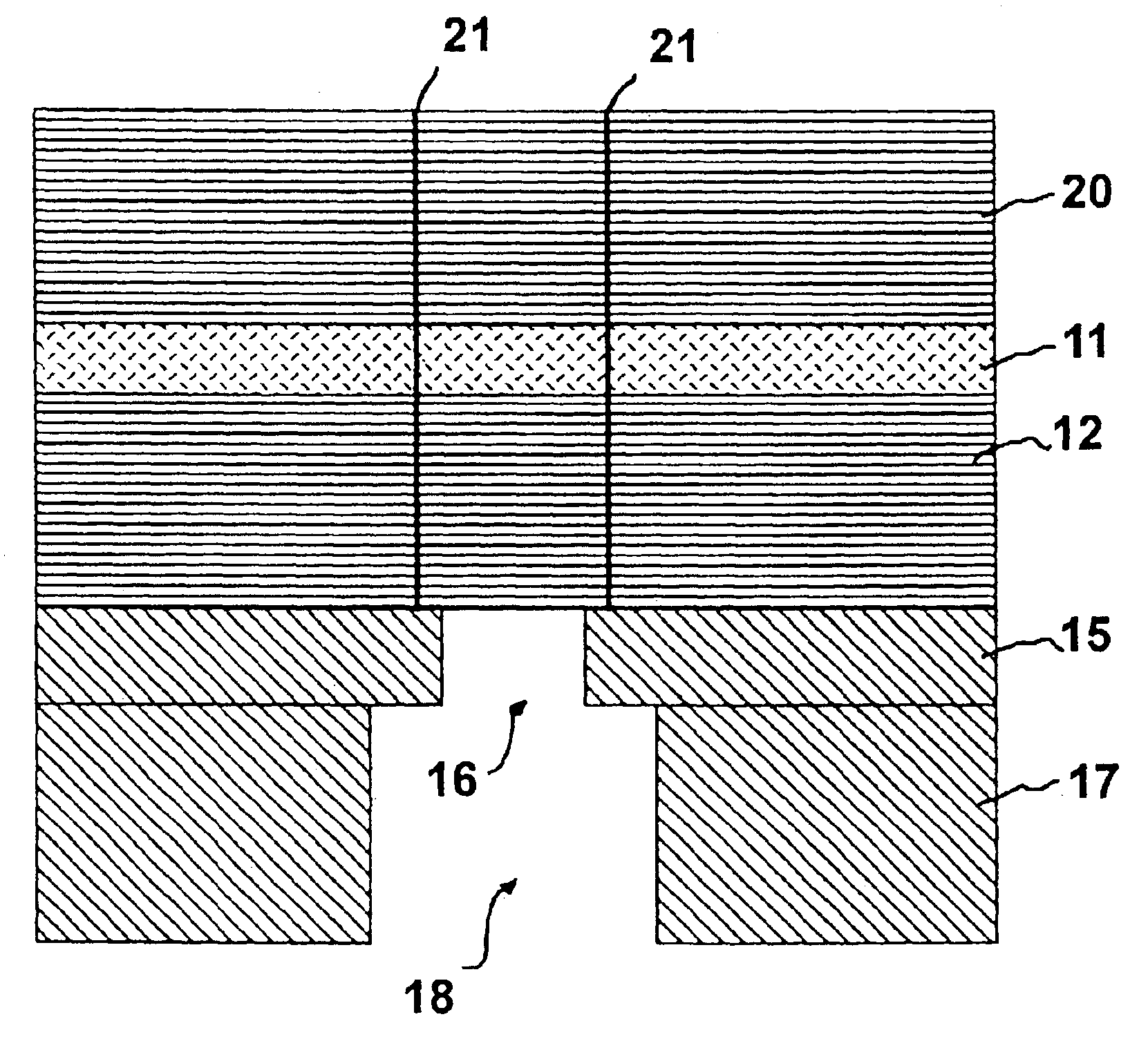
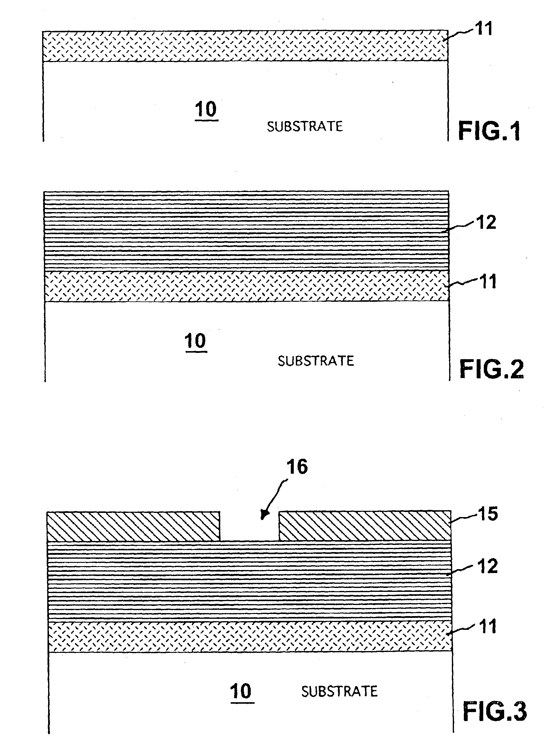
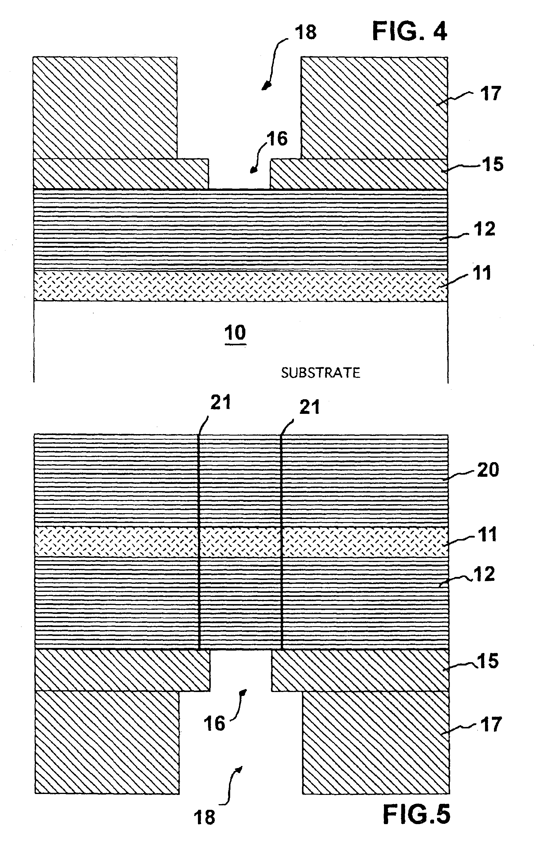
[0016]FIGS. 1 through 5 are simplified sectional views illustrating sequential steps in a method of fabricating VCSELs in accordance with the present invention; and

[0017]FIGS. 6 through 8 are simplified sectional views illustrating sequential steps in another method of fabricating VCSELs in accordance with the present invention.

DESCRIPTION OF THE PREFERRED EMBODIMENTS

[0018]Turning now to FIGS. 1 through 5, various steps are illustrated, sequentially, in a method of fabricating vertical cavity surface emitting lasers (VCSELs) in accordance with the present invention. Referring specifically to FIG. 1, a substrate 10 is provided which may be, for example a semiconductor wafer or the like. A long-wavelength active region 11 is formed on the upper surface of substrate 10 in any well known process. Generally, active region 11 includes one or more quantum well layers with barrier layers therebetween and claddi...


PUM


Abstract

A long-wavelength VCSEL, and method of fabrication, includes a long-wavelength active region epitaxially grown on a compatible substrate with a high heat conductivity DBR mirror stack metamorphically grown on the active region. A supporting substrate is bonded to the DBR mirror stack and the compatible substrate is removed. A second mirror stack, either a DBR or a dielectric mirror stack, is formed on the opposite surface of the active region. Preferably, an InP based active region is grown on an InP based substrate and an AlAs/GaAs based metamorphic DBR mirror stack is metamorphically grown on the active region. The supporting substrate may be either an InP based substrate bonded to the active region or a layer of plated metal, such as copper, silver, gold, nickel, aluminum, etc.

Description

[0002]This application is a division, of application Ser. No. 09 / 642,359, filed 21 Aug. 2000, U.S. Pat. No. 6,628,685.FIELD OF THE INVENTION[0003]This invention relates to a method of fabricating a vertical cavity surface emitting laser which is capable of emitting long-wavelength light and to the vertical cavity surface emitting laser.BACKGROUND OF THE INVENTION[0004]Vertical cavity surface emitting lasers (VCSELs) include first and second distributed Bragg reflectors (DBRS) formed on opposite sides of an active area. The VCSEL can be driven or pumped electrically by forcing current through the active area or optically by supplying light of a desired frequency to the active area. Typically, DBRs or mirror stacks are formed of a material system generally consisting of two materials having different indices of refraction and being easily lattice matched to the other portions of the VCSEL. In conventional VCSELs, convention material systems perform adequately.[0005]However, new produc...

Claims


Application Information

Patent Timeline
Patent Type & Authority Patents(United States)
IPC IPC(8): H01S5/323H01S5/00H01S5/183H01S5/343H01S5/024
CPCB82Y20/00H01S5/34306H01S5/18361H01S5/02461H01S5/041H01S5/02476
Inventor SHIEH, CHAN-LONG
Owner JDS UNIPHASE CORP
Why Eureka
Try Eureka