Welding gun having a removable nozzle end portion and method for operating same

a technology of nozzle end portion and nozzle, which is applied in the field of welding gun, can solve the problems of threads contaminating the threads, threads may experience galling, and the design of threadless contact tip designs

Inactive Publication Date: 2005-02-08
ILLINOIS TOOL WORKS INC
View PDF12 Cites 32 Cited by
  • Summary
  • Abstract
  • Description
  • Claims
  • Application Information

AI Technical Summary

Problems solved by technology

Unfortunately, there are a number of problems associated with existing threadless contact tip designs.
In addition, molten spatter from the weld may deposit on the end of the nozzle, eventually requiring replacement of the nozzle.
However, weld spatter may contaminate the threads or the threads may experience galling, requiring a tool, such as a wrench, to remove the threaded end section from the nozzle body.

Method used


Image

  • Welding gun having a removable nozzle end portion and method for operating same
  • Welding gun having a removable nozzle end portion and method for operating same
  • Welding gun having a removable nozzle end portion and method for operating same

Examples


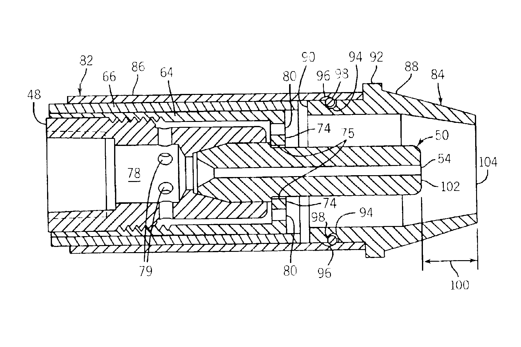
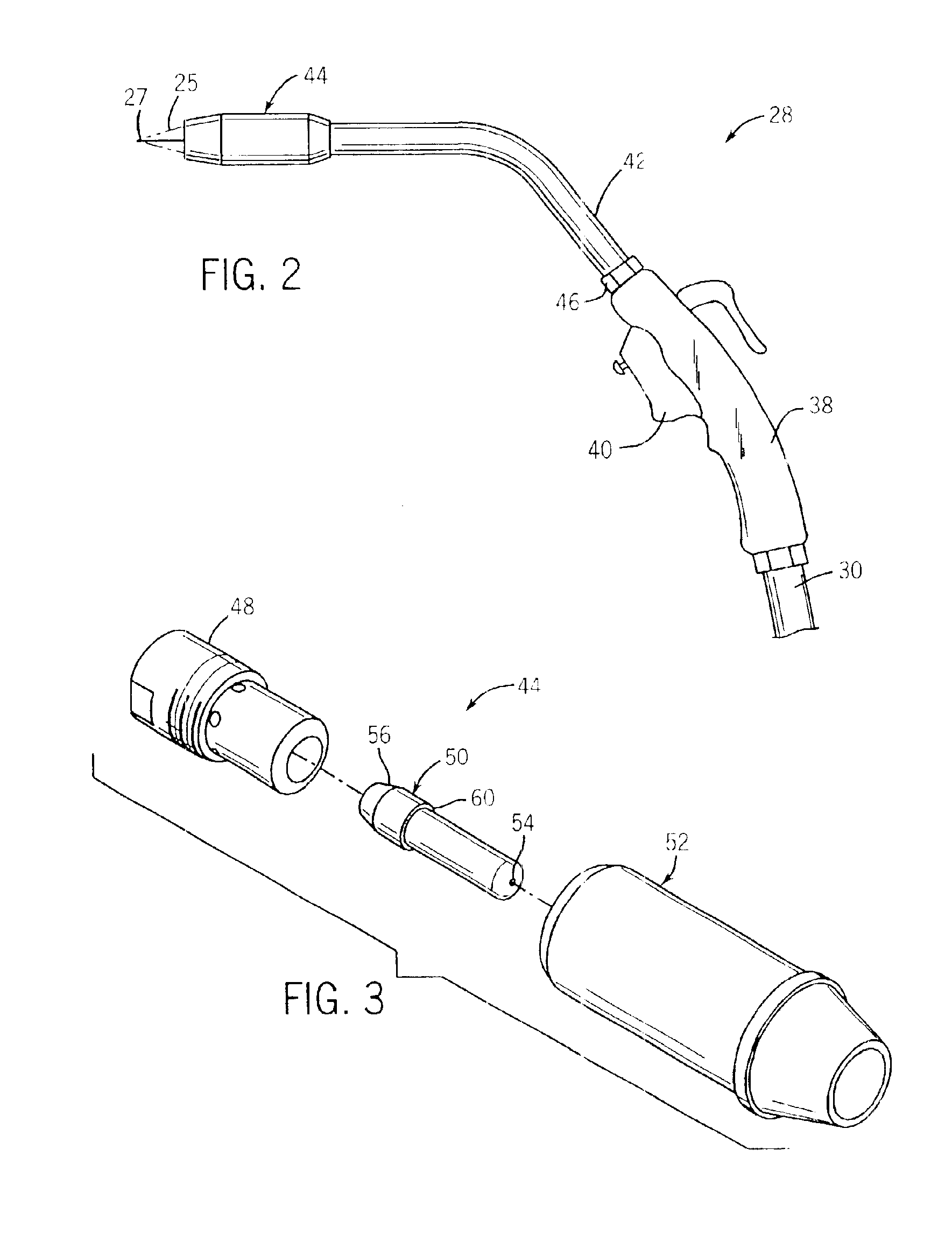
Embodiment Construction

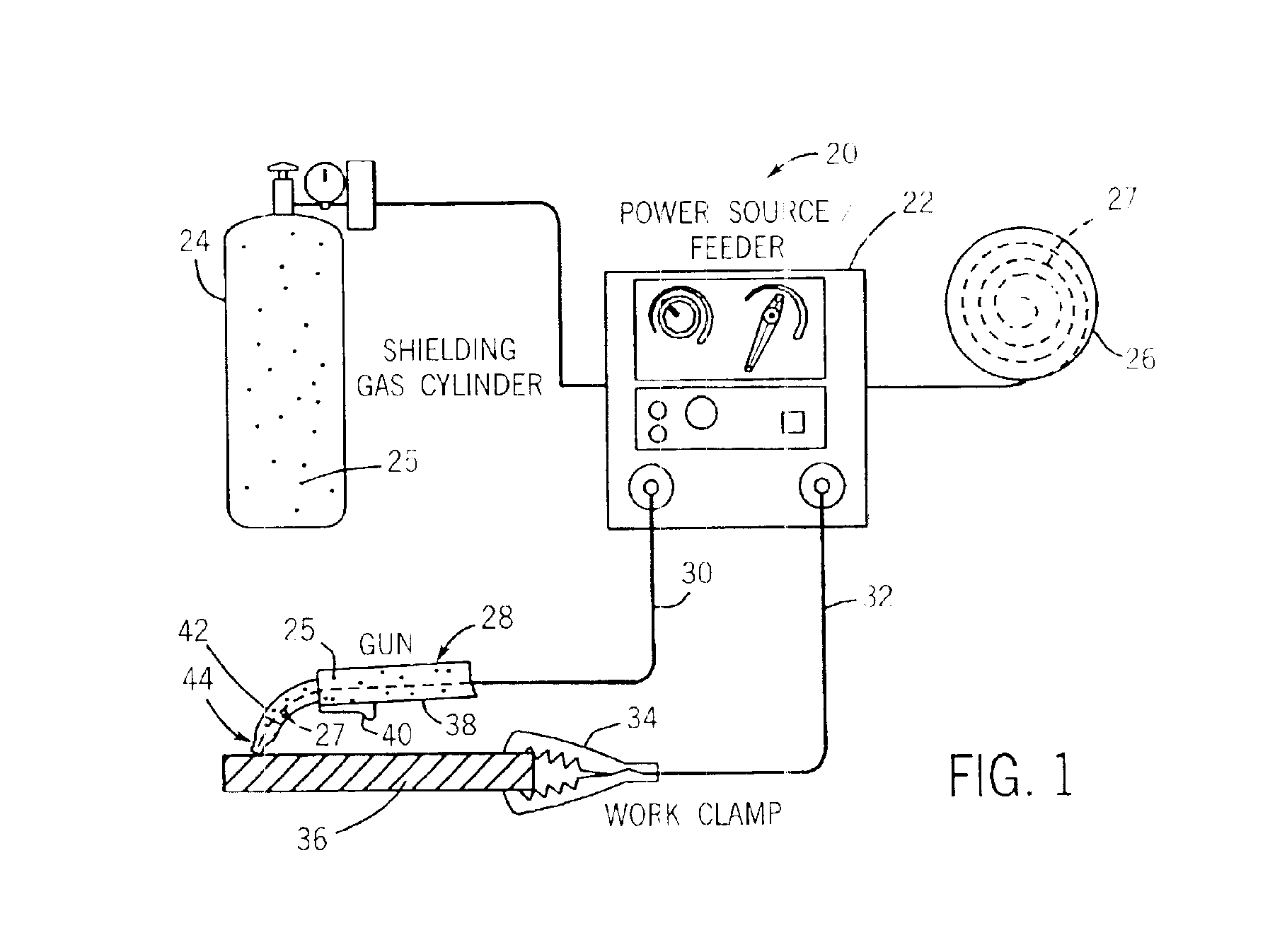
Referring generally to FIG. 1, an exemplary metal inert gas (“MIG”) welding system 20 is illustrated. However, the present technique may be used in other wire feed welding systems, such as submerged arc welding. The illustrated MIG welding system 20 comprises a power source / wire feeder 22, a gas cylinder 24 containing a gas 25, a spool 26 of electrode wire 27, a welding gun 28, a welding cable 30, a work clamp 32, and a ground cable 34. In the illustrated embodiment, the gas 25 and wire 27 are routed from the power source / wire feeder 22 to the welding cable 30. The welding cable 30, in turn, routes the gas 25 and the wire 27 to the welding gun 28. The power source / wire feeder 22 also may be comprised of a separate power source and a separate wire feeder.

The welding cable 30 also has conductors (not shown) for conveying large amounts of electric current from the power source / wire feeder 22 to the welding gun 28. The power source / wire feeder 22 is operable to control the feeding of wi...


PUM

PropertyMeasurementUnit
linear movementaaaaaaaaaa
conical shapeaaaaaaaaaa
compressibleaaaaaaaaaa

Abstract

A welding gun having a removable end portion. The end portion may be adapted to direct gas from the welding gun. The end portion may be conical-shaped. The end portion may be removed without tools. The end portion also may be adapted to be secured to and/or removed from the welding gun in a linear movement. A method of assembling a welding gun. The method may comprise urging a nozzle end member and a nozzle body into engagement to secure the nozzle end member to the nozzle body.

Description

FIELD OF THE INVENTIONThe present invention relates generally to welding systems, and particularly to a welding gun having a nozzle adapted to direct gas flow from the welding gun.BACKGROUND OF THE INVENTIONWelding is a method of joining, or separating, metal objects. Arc welding is a common type of welding. An arc welding system typically is comprised of a power supply coupled by an electrical cable to a welding gun housing an electrode. A ground cable is used to connect the metal object to the power supply. When the electrode is placed against the metal object, the electrode in the welding handle completes an electrical circuit between the power supply and the metal object, allowing electrical current to flow through the electrode and metal object. The electrical current produces an arc between the electrode and the metal object. The heat of the electric arc melts the metal object in the region surrounding the electric arc. A filler material may be added to the molten metal. For e...

Claims


Application Information

Patent Timeline
Patent Type & Authority Patents(United States)
IPC IPC(8): B23K9/00B23K9/173B23K9/24B23K9/26B23K9/32B23K9/29B23K9/16
CPCB23K9/295
Inventor GIESE, WILLIAM R.
Owner ILLINOIS TOOL WORKS INC
Why Eureka
Try Eureka