Converter circuit

a technology of converter circuit and converter, which is applied in the direction of electrical control, instrumentation, and electromechanical/electrostrictive device details, etc., can solve the problems of inability to transfer the energy stored in the smoothing capacitor or consumer to the current source, short injection time of typically 0.5 ms, and high cost, so as to achieve cost saving, light construction, and small size

Inactive Publication Date: 2005-02-08
SIEMENS AG
View PDF12 Cites 15 Cited by
  • Summary
  • Abstract
  • Description
  • Claims
  • Application Information

AI Technical Summary

Benefits of technology

With a preferred form of embodiment, an air coil is used for the storage inductor. Cost savings can be achieved by doing away with the bu

Problems solved by technology

The stratified charge produces an extremely late injection time point during the compression phase of the engine and an extremely short injection time of ty

Method used


Image

  • Converter circuit
  • Converter circuit
  • Converter circuit

Examples


Embodiment Construction

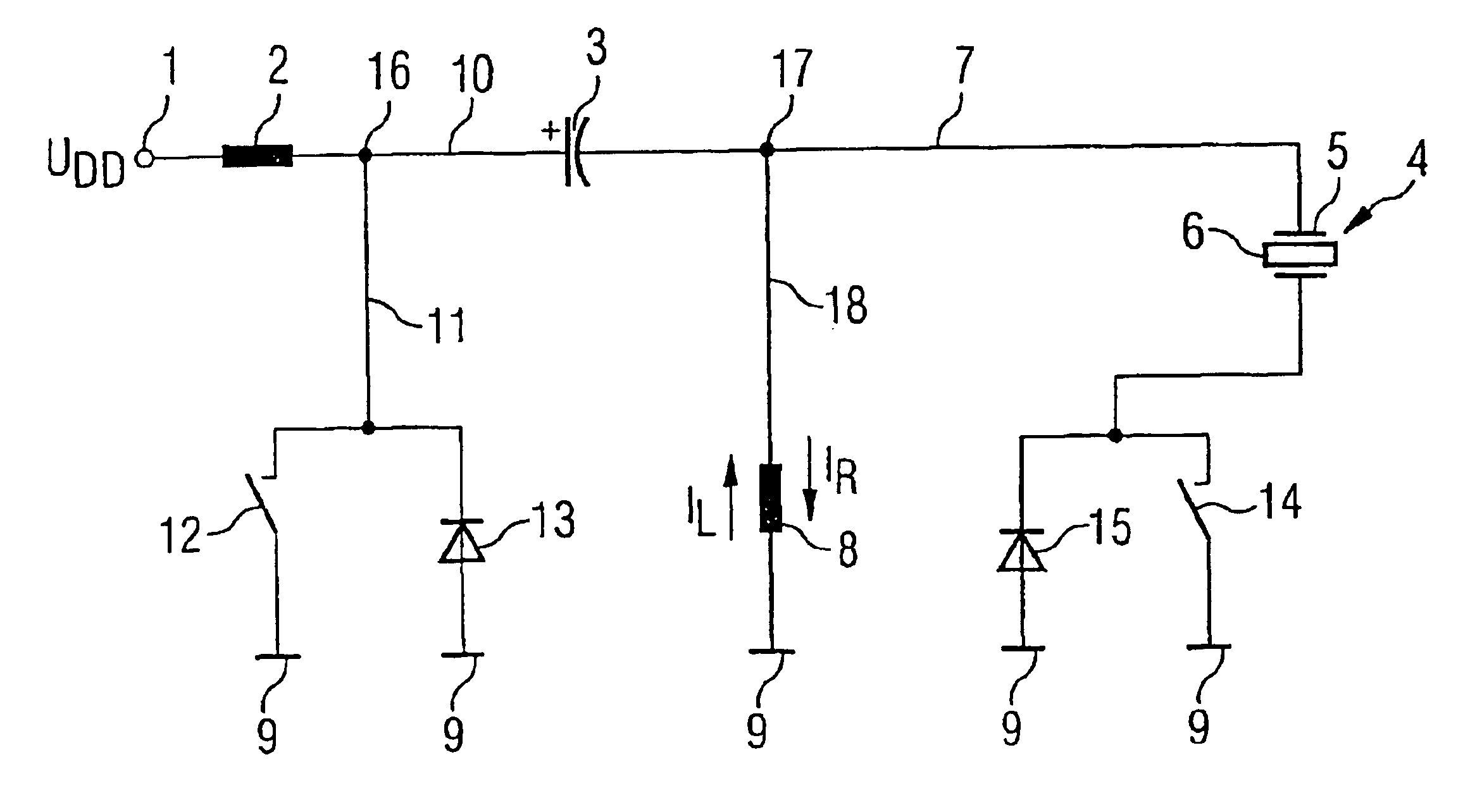
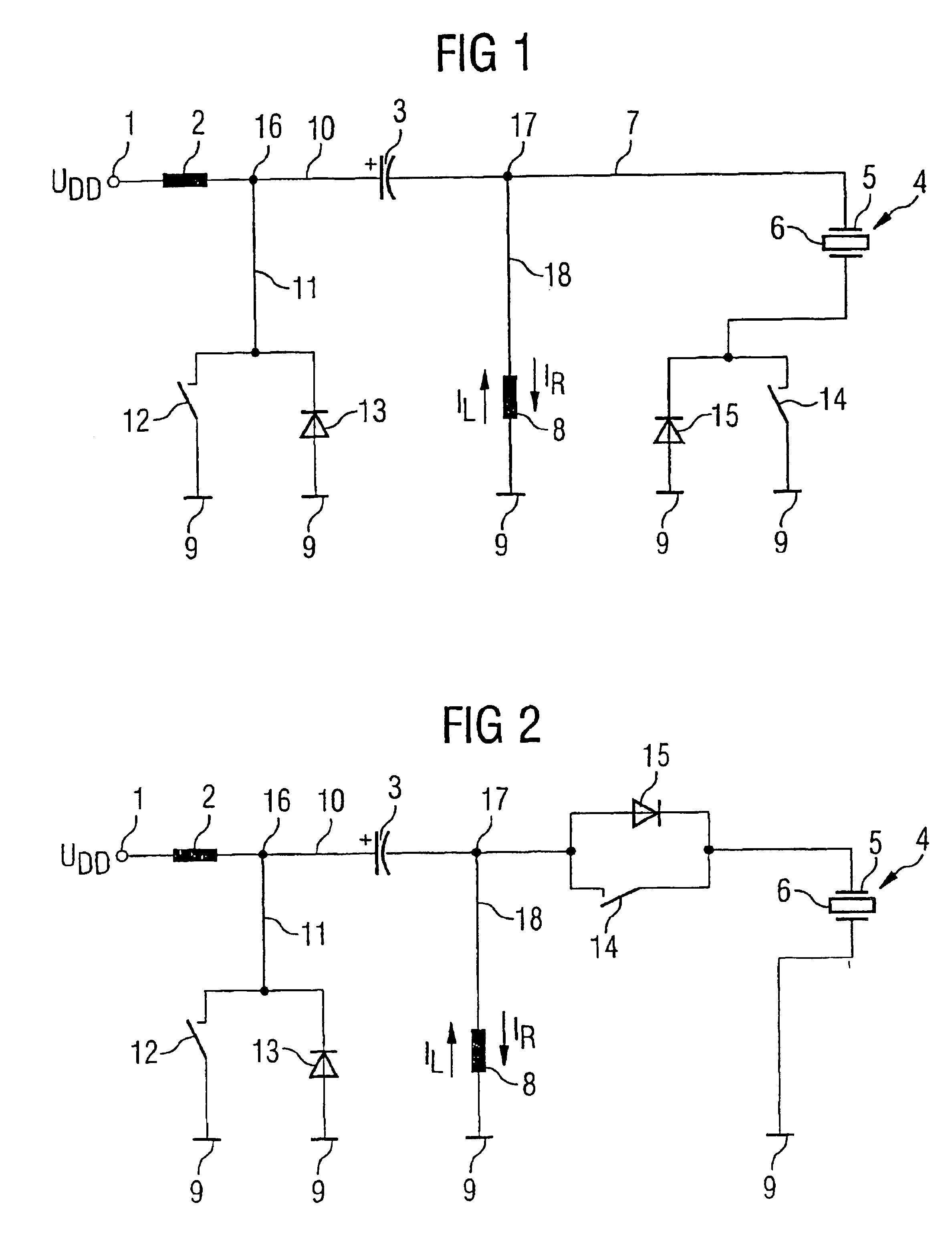
The converter circuit in FIG. 1 has a supply connection 1 downstream of which a filter reactor 2 is connected. The end of the filter reactor 2 away from the supply connection 1 is connected to a primary storage capacitor 3, for example a condenser, and to a secondary storage capacitor 4, for example a piezoelectric actuator. These piezoelectric actuators have a stack of piezoelectric material 6 embedded between electrodes 5, the expansion of which changes when an external voltage is applied. For simplicity, only a single layer of the piezoelectric material with the associated electrodes 5 is shown in FIG. 4.

At a line 7 between the primary storage capacitor 3 and the secondary storage capacitor 4, a storage inductor 8 is connected at its end away from line 7 is connected to ground 9. From a line 10 connecting the filter reactor 2 with the primary storage capacitor 3, a line 11 then branches off leading to a primary switching element 12. The end of the primary switching element 12 awa...


PUM


Abstract

A converter mounting comprises a memory coil inductance (8), a memory primary capacitor (3) mounted upstream of said coil inductance, and a memory secondary capacitor (4), in particular, a piezoelectric actuator, mounted downstream of said coil inductance. Through control of a primary circuit element (12) and of a secondary circuit element (14), the energy of the memory primary capacitor (3) can be transferred to the memory secondary capacitor (4) and recovered.

Description

TECHNICAL FIELD OF THE INVENTIONThe invention relates to a converter circuit with a storage inductor that is connected at one end to a reference potential and at the opposite input end to a supply connection and at the output end to a secondary storage capacitor, the output of which is connected to the reference potential.DESCRIPTION OF THE RELATED ARTDue to the urgent requirement for fuel-saving engines, direct-injection spark-ignition engines with a lean-burn characteristic are presently being developed, because with these engines an average fuel saving of up to 15% can be expected compared with conventional engines controlled to λ=1 with direct injection of the fuel into the inlet manifold. A charge stratification takes place in the combustion chamber under partial load. This means that the combustion chamber is divided into two zones, i.e. a first zone with a combustible fuel-air mixture close to the spark plug and a second zone consisting of air and residual exhaust gas that su...

Claims


Application Information

Patent Timeline
IPC IPC(8): F02D41/20H01L41/00H02M3/155H02M3/04H01L41/04H02M3/07H02N2/00H02N2/06
CPCF02D41/2096H02N2/067H02M3/155F02D2041/201H02M2001/007F02D2041/2051H02M1/007
Inventor BACHMAIER, GEORGFISCHER, BERNHARDKAPPEL, ANDREASULIVIERI, ENRICO
Owner SIEMENS AG
Why Eureka
Try Eureka