PLL circuit including a voltage controlled oscillator and a method for controlling a voltage controlled oscillator

a voltage control and oscillator technology, applied in pulse generators, pulse techniques, instruments, etc., can solve the problems of narrowing the logic range of pll circuits and small margin for manufacturing differences

Inactive Publication Date: 2005-02-08
MONTEREY RES LLC
View PDF5 Cites 31 Cited by
  • Summary
  • Abstract
  • Description
  • Claims
  • Application Information

AI Technical Summary

Benefits of technology

In one aspect of the present invention, a voltage controlled oscillator includes an oscillation unit which generates an output signal having an oscillation frequency corresponding to a control voltage in one of a plurality of oscillation frequency bands. The oscillation unit includes a switching unit which selects one of the plurality of oscillation frequency bands in accordance with a switching signal. A control unit is connected to the switching unit which generates the switching signal in accordance with the control voltage.

Problems solved by technology

However, this narrows the logic range of the PLL circuit.
Further, when the oscillation frequency band is not included in a predetermined range due to manufacturing differences, the margin for manufacturing differences may become small.

Method used


Image

  • PLL circuit including a voltage controlled oscillator and a method for controlling a voltage controlled oscillator
  • PLL circuit including a voltage controlled oscillator and a method for controlling a voltage controlled oscillator
  • PLL circuit including a voltage controlled oscillator and a method for controlling a voltage controlled oscillator

Examples


Embodiment Construction

In the drawings, like numerals are used for like elements throughout.

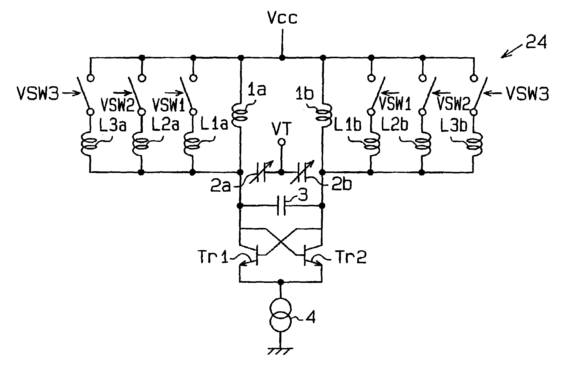
FIG. 4 is a schematic block diagram of a VCO 18 according to a preferred embodiment of the present invention. The VCO 18 includes an oscillation unit 23 and a control unit 28. The oscillation unit 23 generates an output signal OUTVCO having a predetermined oscillation frequency fVCO in accordance with a control voltage VT. The oscillation unit 23 includes a switching unit 24 for selecting one of a plurality of oscillation frequency bands. The control unit 28 generates a switching signal VSW in accordance with the control voltage VT.

FIG. 12 shows a PLL circuit 100 incorporating the VCO 18. The oscillator 11 generates a reference clock signal CK having an inherent frequency in accordance with the oscillation of a crystal oscillation element to generate a reference clock signal CK. The oscillator 11 then provides the reference clock signal CK to a reference divider 12. The reference divider 12 includes a counter circu...


PUM


Abstract

A voltage controlled oscillator having a wide oscillation frequency band, desirable carrier-noise characteristic, and desirable linearity of the oscillation frequency relative to a control voltage. The voltage controlled oscillator includes an oscillation unit and a control unit. The oscillation unit generates an output signal having an oscillation frequency corresponding to the control voltage in one of a plurality of oscillation frequency bands. The oscillation unit includes a switching unit for selecting one of the plurality of oscillation frequency bands in accordance with a switching signal. The control unit generates the switching signal in accordance with the control voltage.

Description

CROSS-REFERENCE TO RELATED APPLICATIONThis application is based upon and claims the benefit of priority from Japanese Patent Application No. 2002-155653, filed on May 29, 2002, the entire contents of which are incorporated herein by reference.BACKGROUND OF THE INVENTIONThe present invention relates to a voltage controlled oscillator used in a phase locked loop circuit.In recent years, there is a demand for mobile communication devices, such as a cellular phone, being more compact, light, and inexpensive.FIG. 1 illustrates a prior art voltage controlled oscillator (VCO) 50. Inductors 1a and 1b each have a first end supplied with power Vcc and a second end connected to variable capacitors 2a and 2b. A control voltage VT is supplied between the variable capacitors 2a and 2b. The capacitances of the variable capacitors 2a and 2b vary in accordance with the control voltage VT.A fixed capacitor 3 and the variable capacitors 2a and 2b are connected in parallel between the inductors 1a and ...

Claims


Application Information

Patent Timeline
Patent Type & Authority Patents(United States)
IPC IPC(8): H03B5/08H03B5/12H03B1/00H03L7/099
CPCH03L7/193H03B5/1293H03B5/1215H03B5/1243H03B5/1265H03B5/1231H03B2201/025H03J2200/10H03K17/22
Inventor YONEKAWA, MASAYUKIDOI, TAKEHITO
Owner MONTEREY RES LLC
Why Eureka
Try Eureka