Three-dimensional measuring method and device, and computer program

a three-dimensional measuring and computer program technology, applied in measurement devices, instruments, computing, etc., can solve problems such as difficulty in heightening resolution, deterioration of phase detection ability, and pixel density of imaging devices, and achieve high speed of measurement and maintain accuracy.

Inactive Publication Date: 2005-02-08
MINOLTA CO LTD
View PDF10 Cites 24 Cited by
  • Summary
  • Abstract
  • Description
  • Claims
  • Application Information

AI Technical Summary

Benefits of technology

The present invention is made in order to solve the above problems, and an object is to provide an improved three dimensional measuring method. Particularly, the object is to provide an improved pattern projection-type three-dimensional measuring method. More concretely, the object is to provide three-dimensional measuring method and device, which are capable of reproducing a three-dimensional shape of an object accurately while maintaining accuracy and high speed of measurement.

Problems solved by technology

This method has two problems.
One is that it is difficult to heighten resolution (measuring accuracy).
However, since the pixel density of an imaging device has a limitation, if the gaps between the stripes are narrowed much, a phase detecting ability is deteriorated due to a rounding error caused by digitization.
The other problem is that it is difficult to make projected stripes correspond to stripes on an image because the stripe pattern is a repeated pattern.
If the correspondence is made improperly, when a shape of the object is reproduced, greatly incorrect result is obtained.
When the gaps between the stripes are widened, the correspondence becomes easy, but the resolution is deteriorated, namely, a trade-off relationship is established.
According to this method, the resolution can be heightened without narrowing the gaps between the stripes, but there is a disadvantage that it takes a long time to shift the phases stably.
Moreover, the problem that the correspondence of the stripes is difficult still remains.
In addition, there suggests a method of projecting a repeated pattern of stripes having three colors R, G and B. However, because it is three-color repeated pattern, positions of stripes cannot be specified only by the colors on the stripes.
However, in the case where discontinuous of stripes exists due to unevenness of the surface of the object a number of stripes cannot be counted properly.

Method used


Image

  • Three-dimensional measuring method and device, and computer program
  • Three-dimensional measuring method and device, and computer program
  • Three-dimensional measuring method and device, and computer program

Examples


first embodiment

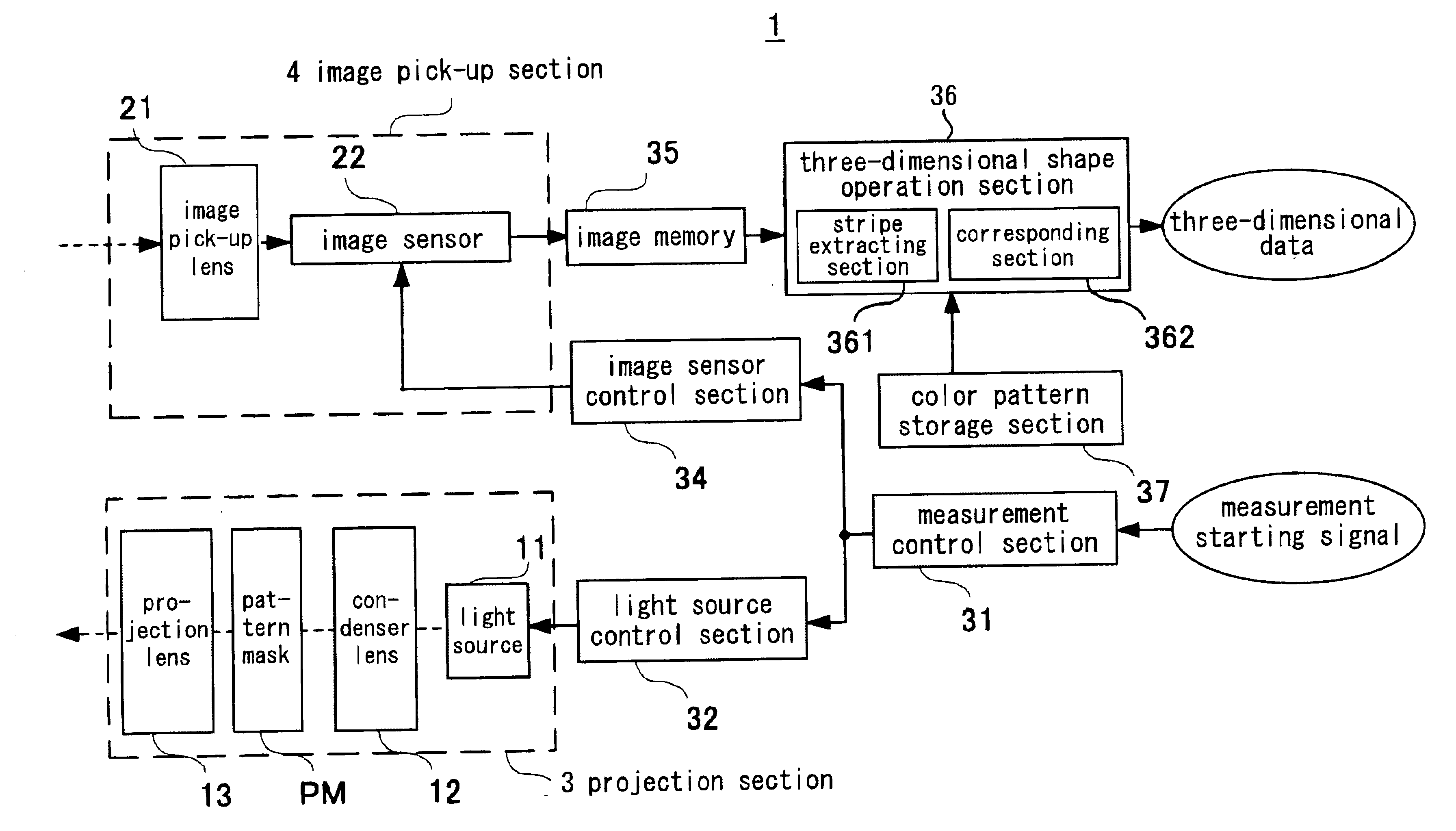
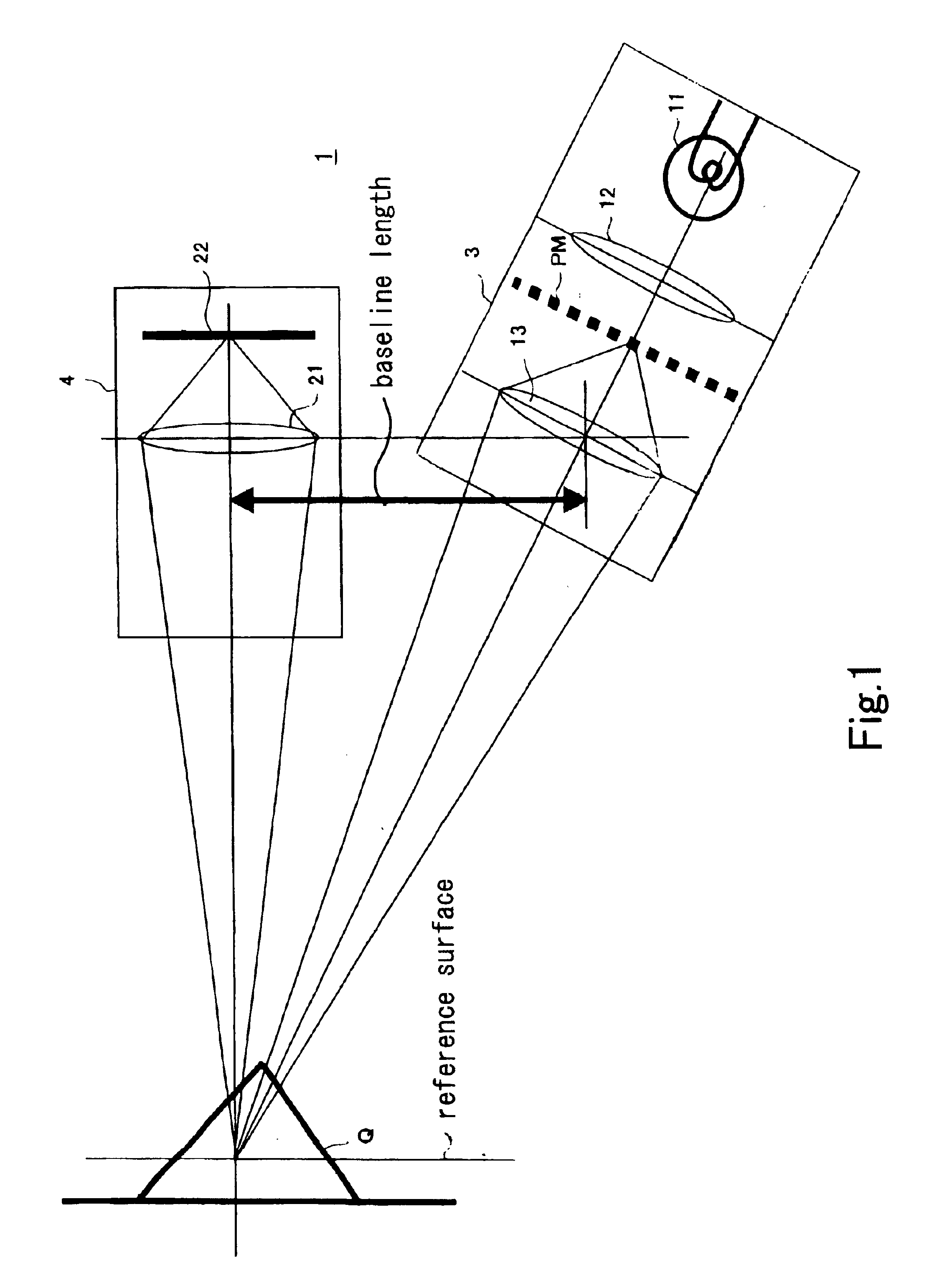
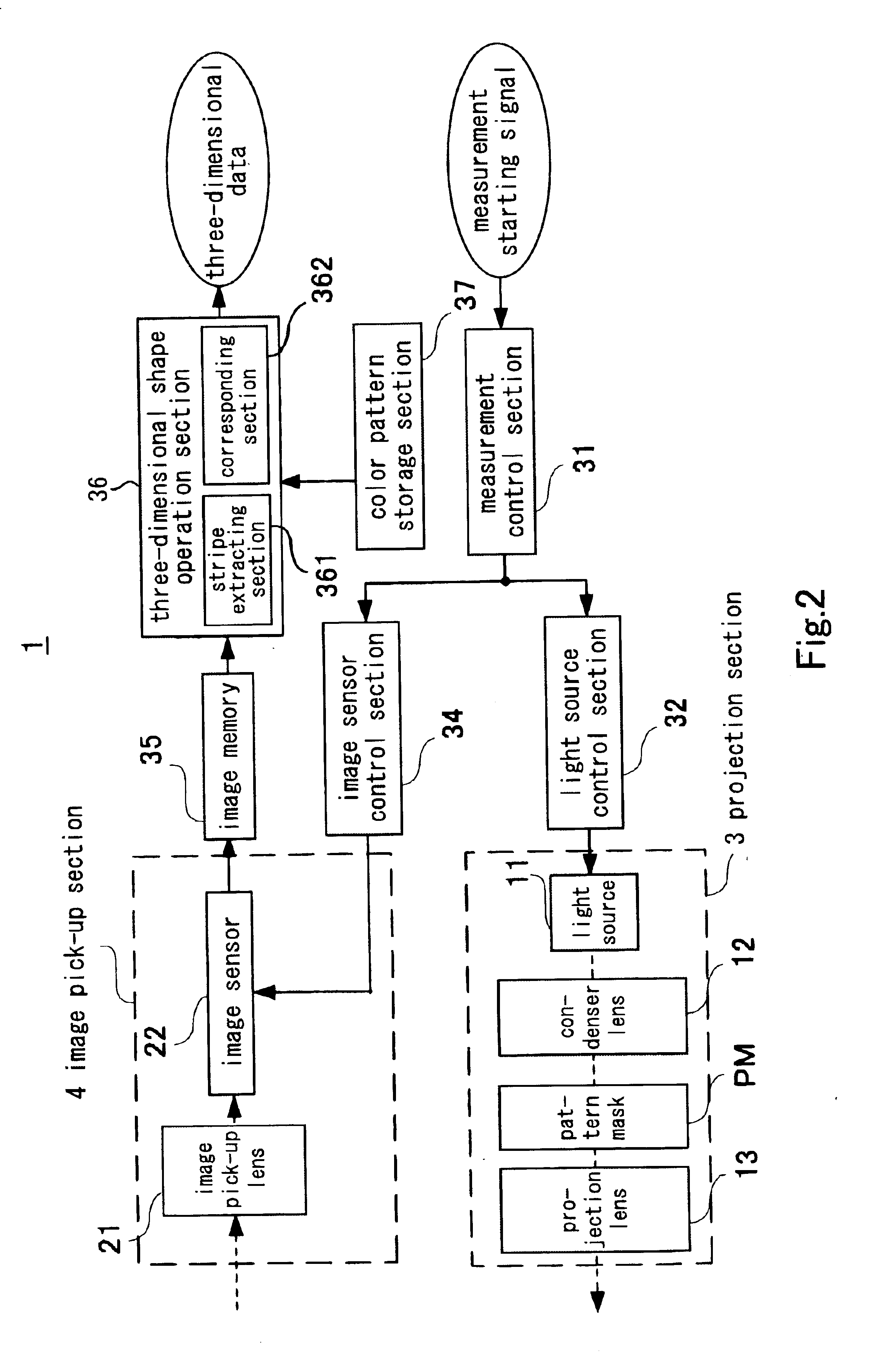
FIG. 1 is a diagram showing a structure of an optical system of a three-dimensional measuring device 1 according to the present invention, and FIG. 2 is a block diagram showing an entire structure of the three-dimensional measuring device.

As shown in FIGS. 1 and 2, the three-dimensional measuring device 1 is provided with a projection section 3 and an image pick-up section 4.

The projection section 3 is provided with a light source 11, a condenser lens 12, a projection lens 13, a pattern mask PM and the like. The light source 11 is a flash light source for emitting a white light. The condenser lens 12 condenses the light emitted from the light source 11.

The pattern mask PM is formed into an oblong shape by a material such as synthetic resin or glass. A stripe pattern SP having colored stripes are formed on the pattern mask PM. In the stripe pattern SP, colors of the respective stripes are coded to be set so that one color pattern composed of plural predetermined numbers of stripes is...

second embodiment

In the first embodiment, arbitrary colors selected from the seven colors are combined, but in the second embodiment arbitrary colors selected from five colors G, C, M, Y and W with a large light quantity are combined. The structure of the second embodiment is the same as that in the first embodiment except that the seven colors are changed into five colors.

FIG. 10 is a diagram showing a light quantity ratio of seven colors, FIG. 11 is a diagram showing an example of a color arrangement of the stripe pattern SP in the second embodiment, and FIG. 12 is a diagram showing a Bayer arrangement.

As shown in FIG. 12, in the color image sensor where primary color filters are Bayer-arranged, a ratio of pixel numbers of each pixel of R, G and B is 1:2:1. In the case where light quantities of the RGB components as the basic colors composing the respective stripes are the same, the stripes having the G component have a large light quantity and a signal with high level can be obtained from the ima...

third embodiment

In the third embodiment, arbitrary colors selected from four colors G, C, Y and W including the G component are combined. The structure here is the same as that in the first embodiment except that the seven colors are changed into the four colors.

FIG. 13 is a diagram showing existence / non-existence of the G component in the seven colors, and FIG. 14 is a diagram showing an example of the color arrangement of the stripe pattern SP in the third embodiment.

As mentioned above, in the image sensor where colors are Bayer-arranged, a pixel number ratio of the RGB pixels is 1:2:1. Moreover, as the pixel density is higher, the measuring accuracy of the stripe positions becomes higher. The stripes having the G component is advantageous because spacial resolution of the image sensor is high.

In order to utilize a light quantity effectively and use the spacial resolution of the image sensor in excelsis, it is ideally desirable that white and black or green and black patterns are repeated. Howeve...


PUM


Abstract

In order to reproduce a three-dimensional shape of an object accurately while maintaining measuring accuracy and high speed, in a three-dimensional measuring method of projecting a stripe pattern having colored stripes on the object and measuring the three-dimensional shape of the object based on stripe positions on the imaged image corresponding to the stripes on the stripe pattern, colors of the stripes on the stripe pattern are set according to a predetermined rule, and a plurality of stripes having a predetermined positional relationship are extracted from the image, and correspondence with stripes on the stripe pattern based on the color arrangement of the extracted plural stripes.

Description

This application is based on application No. JP 2001-233264 filed in Japan, the content of which is hereby incorporated by reference.BACKGROUND OF THE INVENTION1. Field of the InventionThe present invention relates to an improved three-dimensional measuring method. More concretely, the invention relates to improved pattern projection-type three-dimensional measuring method and device, and a computer program. Particularly, the invention relates to a method of making stripes of a stripe pattern on a pattern mask correspond to stripes on a projected image.2. Description of the Related ArtAs a method of three-dimensionally measuring an object with a high speed, a method of projecting a stripe pattern onto the object is known. In this method, a stripe pattern is projected on an object and is photographed, and a three-dimensional shape of the object is obtained from a deformed state of the stripe pattern on the obtained image. As the stripe pattern, stripes having light quantity distribut...

Claims


Application Information

Patent Timeline
Patent Type & Authority Patents(United States)
IPC IPC(8): G01B11/25G01B11/24
CPCG01B11/2509
Inventor YAHASHI, AKIRAKATAGIRI, TETSUYAYAGI, FUMIYAUCHINO, HIROSHITANAKA, YUZURU
Owner MINOLTA CO LTD
Why Eureka
Try Eureka