Folded, telecentric projection lenses for use with pixelized panels

a projection lens and pixelized panel technology, applied in the field of projection lenses, can solve the problems of lateral color variation, inability to adjust the size across the full field of view, difficulty in adjusting accommodation, etc., and achieve the effect of reducing the system's overall size, reducing contrast, and high level of chromatic aberration correction

Inactive Publication Date: 2005-02-08
3M INNOVATIVE PROPERTIES CO
View PDF22 Cites 123 Cited by
  • Summary
  • Abstract
  • Description
  • Claims
  • Application Information

AI Technical Summary

Benefits of technology

The effective back focal length (BFL) of a projection lens / pixelized panel combination is the distance between the front surface of the pixelized panel and the vertex of the back surface of the rearward-most lens element of the projection lens which has optical power when (1) the image of the pixelized panel is located at infinity and (2) the projection lens is located in air, i.e., the space between the rearward-most lens element of the projection lens and the pixelized panel is filled with air as opposed to the glasses making up the prisms, beam splitters, etc. normally used between a projection lens and a pixelized panel.
Projection systems are used to form an image of an object on a viewing screen. Such systems can be of the front projection or rear projection type, depending on whether the viewer and the object are on the same side of the screen (front projection) or on opposite sides of the screen (rear projection).
For front projection systems, the viewer will be on the left side of screen 16 in FIG. 4, while for rear projection systems, the viewer will be on the right side of the screen. For rear projection systems which are to be housed in a single cabinet, one or more mirrors are often used between the projection lens and the screen to fold the optical path and thus reduce the system's overall size.
A high level of chromatic aberration correction is important because color aberrations can be easily seen in the image of a pixelized panel as a smudging of a pixel or, in extreme cases, the complete dropping of a pixel from the image. Lateral color, i.e., the variation of magnification with color, is particularly troublesome since it manifests itself as a decrease in contrast, especially at the edges of the field. In extreme cases, a rainbow effect in the region of the full field can be seen.
In projection systems employing CRTs a small amount of (residual) lateral color can be compensated for electronically by, for example, reducing the size of the image produced on the face of the red CRT relative to that produced on the blue CRT. With a pixelized panel, however, such an accommodation cannot be performed because the image is digitized and thus a smooth adjustment in size across the full field of view is not possible. A higher level of lateral color correction, including correction of secondary lateral color, is thus needed from the projection lens.
When a panel is offset, the distortion at the viewing screen does not vary symmetrically about a horizontal line through the center of the screen but can increase monotonically from, for example, the bottom to the top of the screen. This effect makes even a small amount of distortion readily visible to the viewer.

Problems solved by technology

Lateral color, i.e., the variation of magnification with color, is particularly troublesome since it manifests itself as a decrease in contrast, especially at the edges of the field.
With a pixelized panel, however, such an accommodation cannot be performed because the image is digitized and thus a smooth adjustment in size across the full field of view is not possible.
The use of a pixelized panel to display data leads to stringent requirements regarding the correction of distortion.
Because the operation of DMDs and reflective LCDs depend upon their ability to reflect light efficiently, projection systems employing panels of these types are particularly susceptible to ghost problems.
This makes the lens asymmetric about the aperture stop which makes the correction of lateral color more difficult.
The requirement for a large field of view makes it even more difficult to correct the lateral color of the lens.
This is especially so when combined with the requirement for a long effective back focal length which itself makes it more difficult to correct lateral color.
Also, as mentioned above, the requirement for telecentricity is a third factor which makes the correction of lateral color challenging.
A construction of this type makes it more difficult to correct the aberrations of the system, especially if the lens is to include only a small number of lens elements as is desired to reduce the cost, weight, and complexity of the projection lens.
Achieving a long back focal length, a wide field of view in the direction of the lens' long conjugate, telecentricity, and a folded configuration, while still maintaining high levels of aberration correction and low levels of ghost generation, is particularly challenging since these various requirements tend to work against one another.
To do so while minimizing the number of lens elements used in the lens is even more demanding.

Method used


Image

  • Folded, telecentric projection lenses for use with pixelized panels
  • Folded, telecentric projection lenses for use with pixelized panels
  • Folded, telecentric projection lenses for use with pixelized panels

Examples


examples

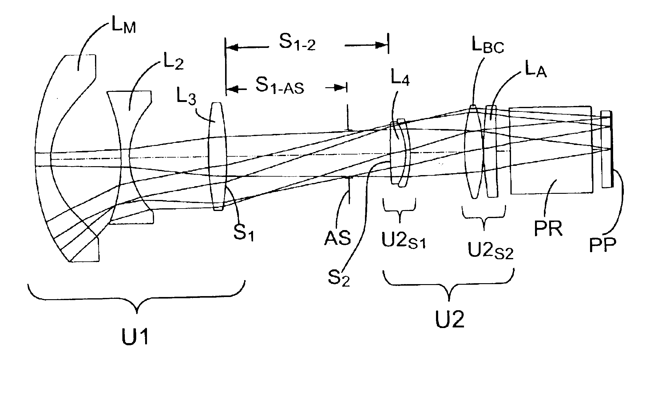
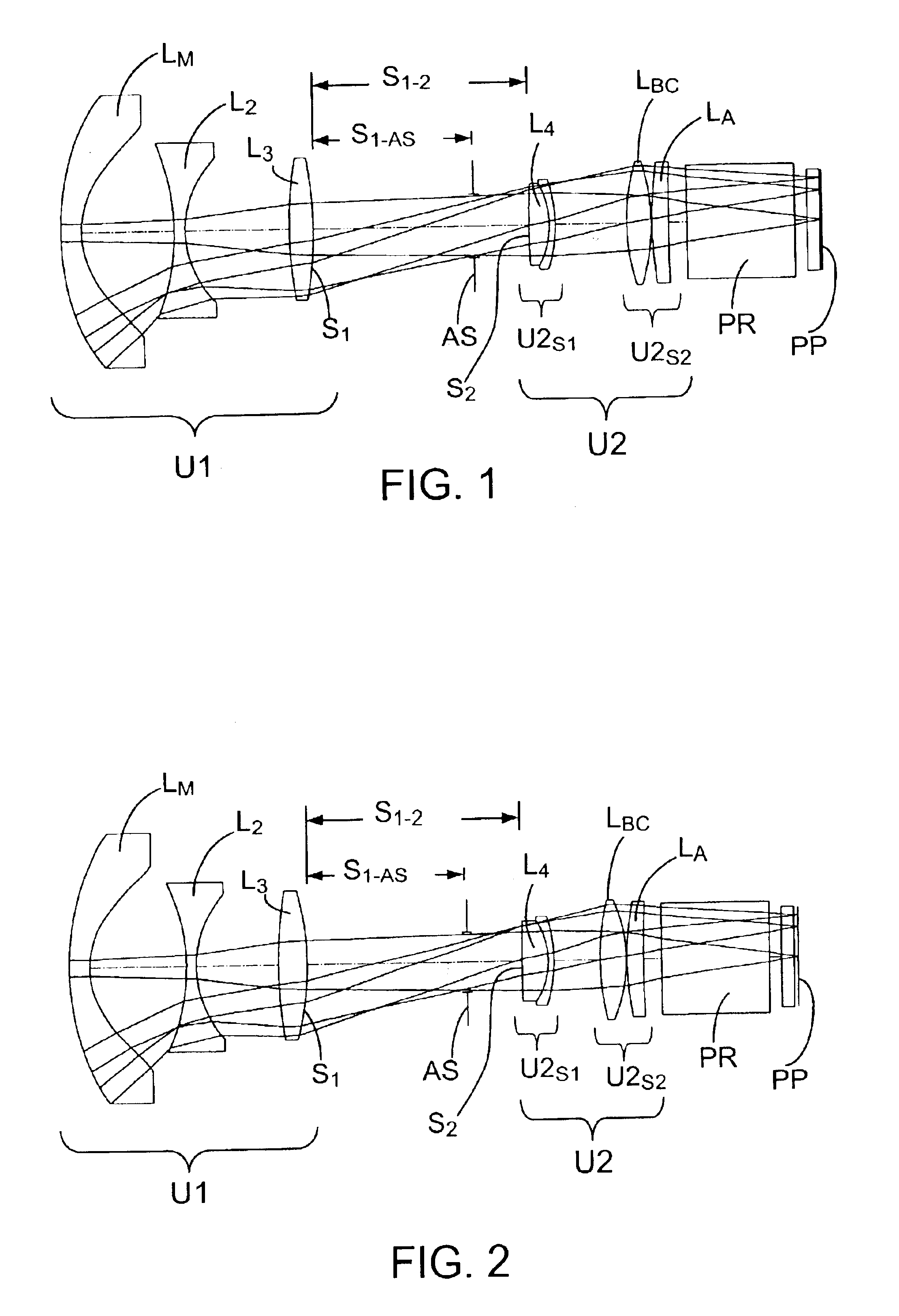
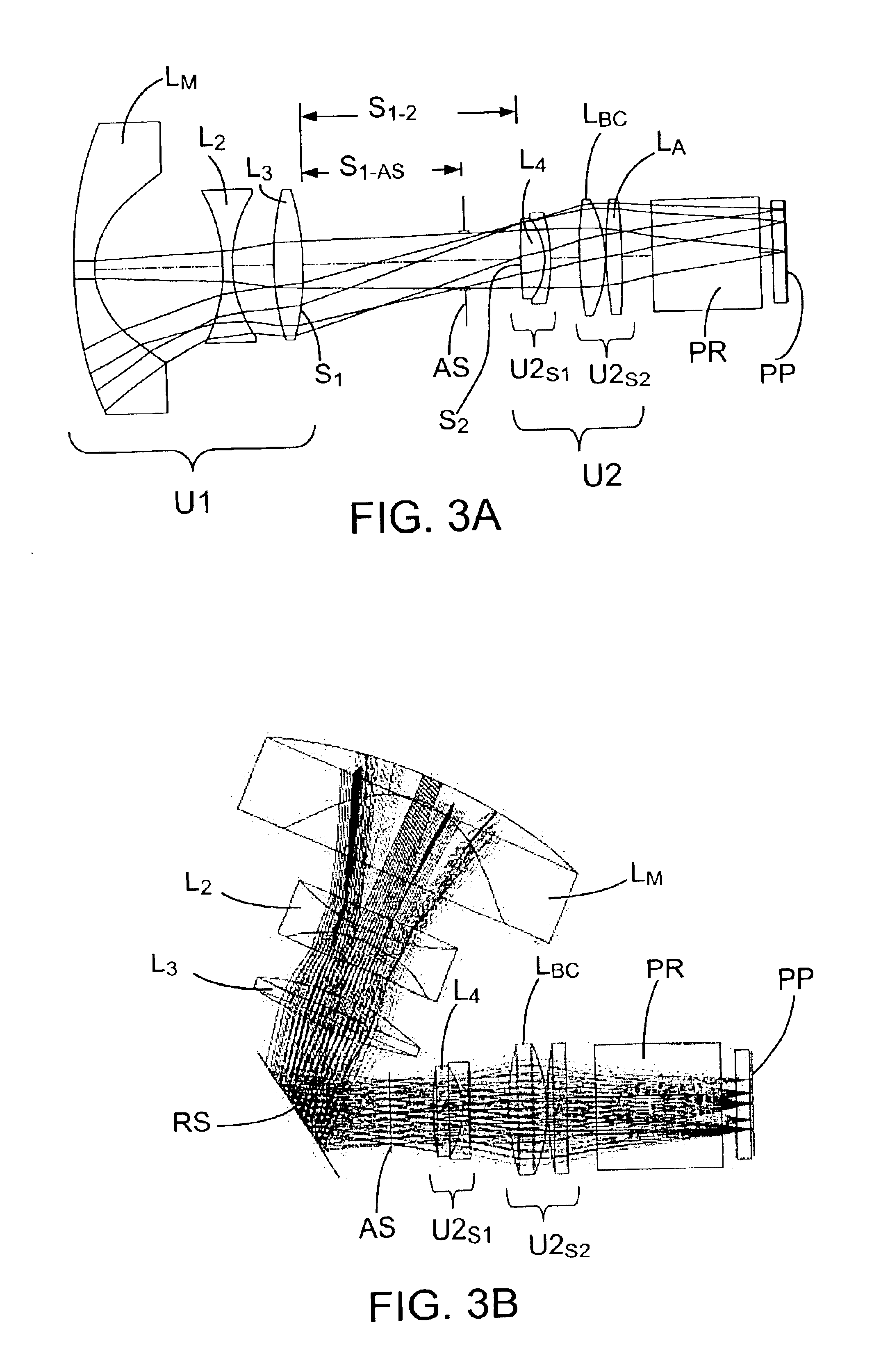
FIGS. 1-3 and Tables 1-3 illustrate representative projection lenses constructed in accordance with the invention.

OHARA designations are used for the various glasses employed in the lens systems. Equivalent glasses made by other manufacturers (e.g., HOYA or SCHOTT) can be used in the practice of the invention. Industry acceptable materials are used for the plastic elements.

The aspheric coefficients set forth in the tables are for use in the following equation: z=cy21+[1-(1+k)⁢ ⁢c2⁢ ⁢y2]1 / 2+Dy4+Ey6+Fy8+Gy10+Hy12+Iy14

where z is the surface sag at a distance y from the optical axis of the system, c is the curvature of the lens at the optical axis, and k is a conic constant, which is zero except where indicated in the prescriptions of Tables 1-3.

The designation “a” associated with various surfaces in the tables represents an aspherical surface, i.e., a surface for which at least one of D, E, F, G, H, or I in the above equation is not zero; and the designation “c” indicates a surface for...


PUM


Abstract

Projection lenses for use with pixelized panels (PP) are provided. The projection lenses have a negative first unit (U1) separated from a positive second unit (U2) by a reflective surface (RS) which folds the lens' optical axis. The lenses are telecentric on the short conjugate side, have a large field of view in the direction of the long conjugate, and have low aberration levels, including, in particular, low levels of lateral color.

Description

FIELD OF THE INVENTIONThis invention relates to projection lenses and, in particular, to folded, telecentric projection lenses for use in forming an image of an object composed of pixels, such as, a DMD, a reflective LCD, a transmissive LCD, or the like.DEFINITIONSAs used in this specification and in the claims, the following terms shall have the following meanings:(1) TelecentricTelecentric lenses are lenses which have at least one pupil at infinity. In terms of principal rays, having a pupil at infinity means that the principal rays are parallel to the optical axis (a) in object space, if the entrance pupil is at infinity, or (b) in image space, if the exit pupil is at infinity.In practical applications, a telecentric pupil need not actually be at infinity since a lens having an entrance or exit pupil at a sufficiently large distance from the lens' optical surfaces will in essence operate as a telecentric system. The principal rays for such a lens will be substantially parallel to...

Claims


Application Information

Patent Timeline
Patent Type & Authority Patents(United States)
IPC IPC(8): G02B13/22G02B13/16G02B13/18G02B9/10G02B9/00
CPCG02B9/10G02B13/22G02B13/18G02B13/16G03B21/26G02B3/00
Inventor KREITZER, MELVYN H.
Owner 3M INNOVATIVE PROPERTIES CO
Why Eureka
Try Eureka