
Methods and apparatus for reading memory device register data

a register data and memory device technology, applied in the field of memory devices, can solve the problems of slowing down the rate at which the processor is able to accomplish its operations, sram cache memory, and remaining components of existing computer systems

Inactive Publication Date: 2005-02-08
ROUND ROCK RES LLC
View PDF13 Cites 7 Cited by
  • Summary
  • Abstract
  • Description
  • Claims
  • Application Information

AI Technical Summary

Benefits of technology

"The patent text discusses the problem of adding readout circuitry to memory devices to read data from registers without using a lot of space on the semiconductor die. This added circuitry can increase manufacturing costs. The technical effect of the patent is to provide a solution for reading register data in memory devices without using a great deal of read-out circuitry."

Problems solved by technology

However, the remaining components of existing computer systems, with the exception of SRAM cache memory, are not capable of operating at the speed of the processor.
The time required for the processor, operating, for example, at 300 MHz, to read data from or write data to a system memory device operating at, for example, 66 MHz, greatly slows the rate at which the processor is able to accomplish its operations.
Thus, much effort has been devoted to increasing the operating speed of system memory devices.
However, even SDRAMs are typically incapable of operating at the clock speed of currently available processors.
Thus, SDRAMs cannot be connected directly to the processor bus, but instead must interface with the processor bus through a memory controller, bus bridge, or similar device.
The disparity between the operating speed of the processor and the operating speed of SDRAMs continues to limit the speed at which processors may complete operations requiring access to system memory.
One of the problems of conventional DRAMs is their relatively low speed resulting from the time required to precharge and equilibrate circuitry in the DRAM array.
The need to add this readout circuitry can be problematic because the large amount of circuitry already present in state of the art memory devices minimizes the space available on a semiconductor die to add this additional circuitry.
Doing so, however, reduces the number of dies that can be manufactured from each wafer, thus increasing the cost of such memory devices.

Method used


Image

  • Methods and apparatus for reading memory device register data
  • Methods and apparatus for reading memory device register data
  • Methods and apparatus for reading memory device register data

Examples


Embodiment Construction

led to the memory array to receive the first set of data bits is coupled to the coupling circuit to receive the third plurality of data bits, and to the external terminals. The data path circuit transmits the data bits received to the external terminals of the memory device.

BRIEF DESCRIPTION OF THE DRAWINGS

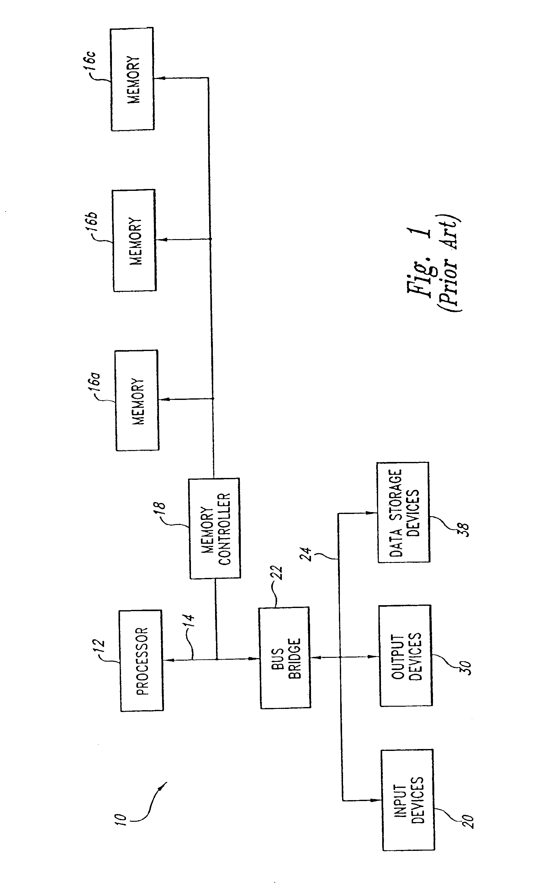
[0025]FIG. 1 is a block diagram of a conventional computer system using a plurality of SLDRAM memory devices.

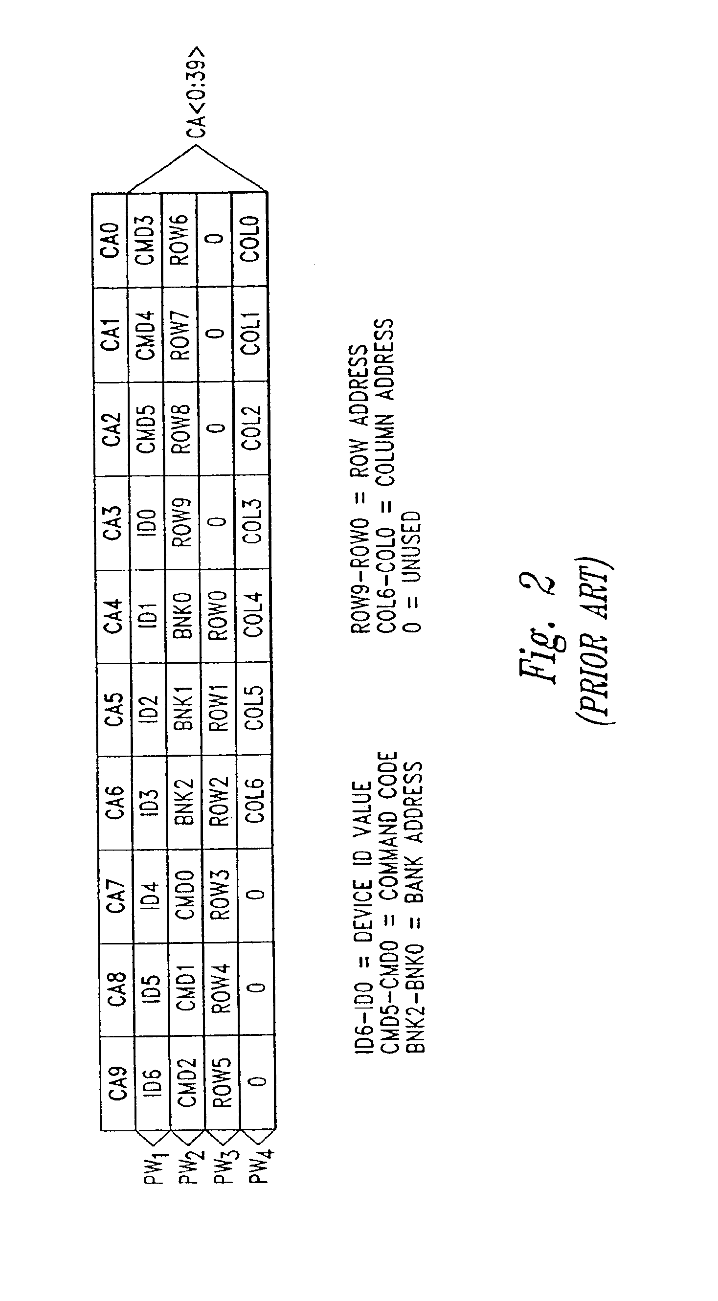
[0026]FIG. 2 is a diagram showing a typical command packet for a SLDRAM.

[0027]FIG. 3 is a block diagram of a conventional packetized DRAM used in the computer system of FIG. 1.

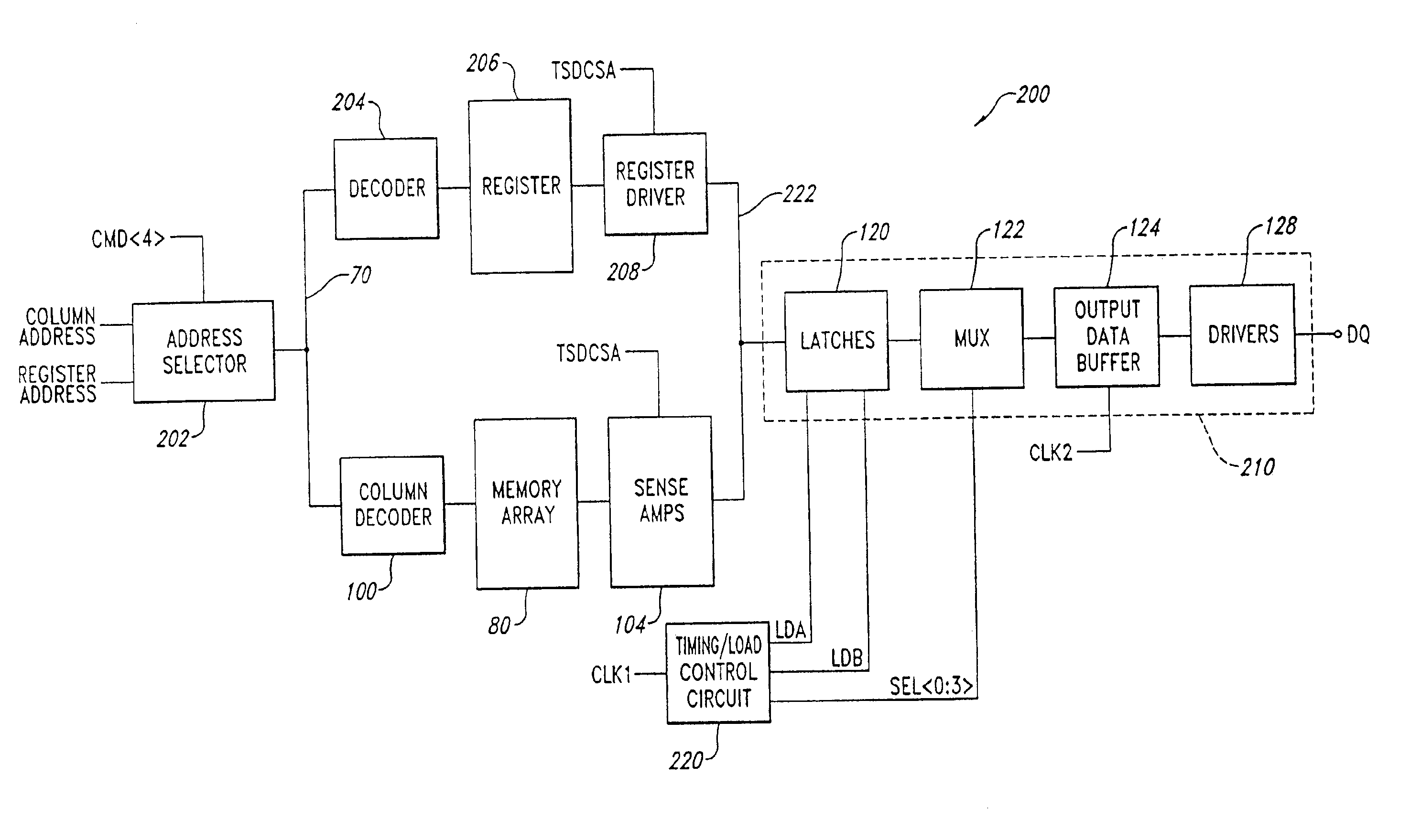
[0028]FIG. 4 is a functional block diagram of a register read system 200 according to one embodiment of the present invention.

[0029]FIG. 5 is a functional block diagram of one embodiment of a command decoder.

[0030]FIG. 6 is a logic diagram and schematic of one embodiment of an address selector.

[0031]FIG. 7 is a logic diagram and schematic of one embodiment of a portion of a register driver.

[0032]FIG. ...


PUM


Abstract

A methods and apparatus for reading register data from a memory device and outputting the register data to external data terminals of the memory device that outputs a first set of data bits from a memory array to the external terminals responsive to a first addressing signal. A register stores data, and outputs a second set of data bits responsive to a second addressing signal. A coupling circuit receives the second set of data bits, processes the data bits, and outputs a third set of data bits corresponding to the second set of data bits responsive to an enabling signal. A data path circuit that is coupled to the memory array to receive the first set of data bits is coupled to the coupling circuit to receive the third plurality of data bits, and to the external terminals. The data path circuit transmits the data bits received to the external terminals of the memory device.

Description

CROSS-REFERENCE TO RELATED APPLICATIONS[0002]This application is a continuation of U.S. patent application Ser. No. 10 / 283,657, filed Oct. 29, 2002, now U.S. Pat. No. 6,654,293 which is a continuation of U.S. patent application Ser. No. 09 / 938,809, filed Aug. 24, 2001, issued Dec. 17, 2002 as U.S. Pat. No. 6,496,420, which is a divisional of U.S. patent application Ser. No. 09 / 571,028, filed May 15, 2000, issued Mar. 26, 2002 as U.S. Pat. No. 6,363,018, which is a divisional of U.S. patent application Ser. No. 09 / 259,225, filed Mar. 1, 1999, issued May 16, 2000 as U.S. Pat. No. 6,064,600.TECHNICAL FIELD[0003]This invention relates generally to memory devices used in computer systems, and more particularly, to methods and apparatus for reading register data from registers within the memory device.BACKGROUND OF THE INVENTION[0004]Conventional computer systems include a processor (not shown) coupled to a variety of memory devices, including read-only memories (“ROMs”) which traditional...

Claims


Application Information

Patent Timeline
Patent Type & Authority Patents(United States)
IPC IPC(8): G11C7/10
CPCG11C7/1051
Inventor MANNING, TROY A.
Owner ROUND ROCK RES LLC
Learn More