
Gas flow method for detection of local preform defects based on statistical analysis

a local preform and statistical analysis technology, applied in the direction of mechanical measurement arrangements, mechanical roughness/irregularity measurements, instruments, etc., can solve the problems of fiber preform distortion, fiber preform misplacement in the mold cavity,

Inactive Publication Date: 2005-02-08
NORTHWESTERN UNIV
View PDF1 Cites 8 Cited by
  • Summary
  • Abstract
  • Description
  • Claims
  • Application Information

AI Technical Summary

Benefits of technology

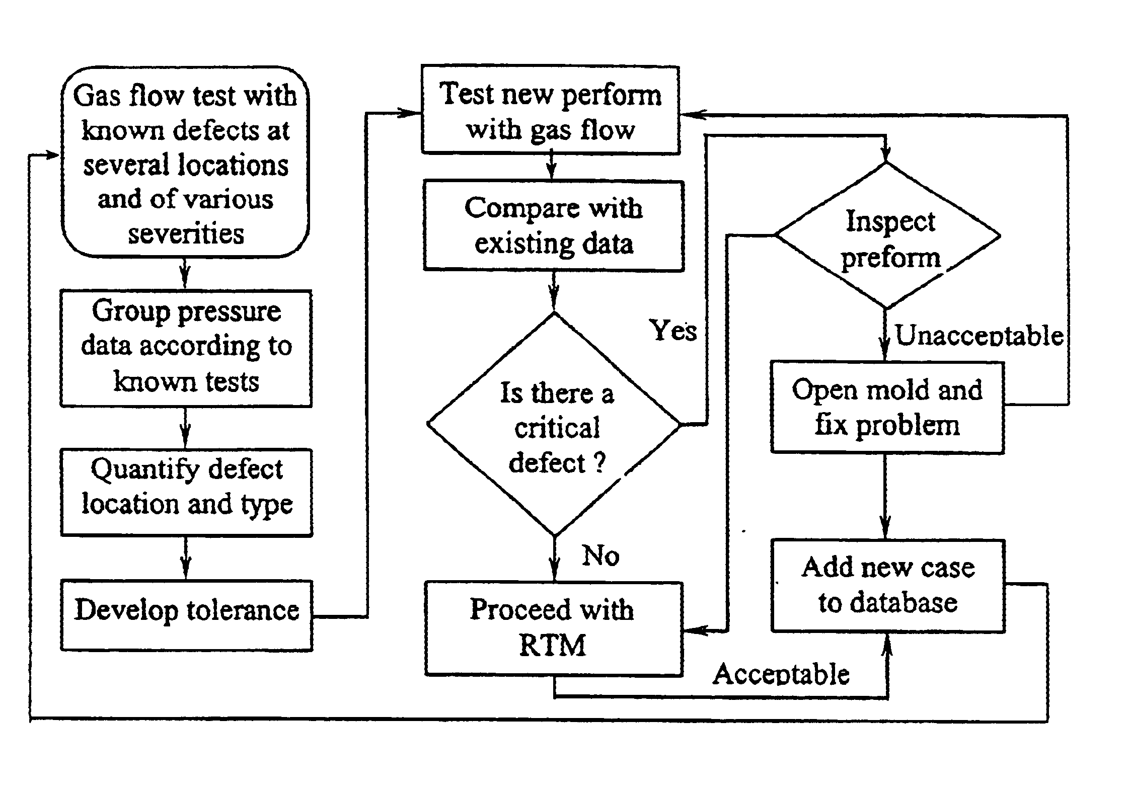
Pursuant to an embodiment of the invention, gas pressures at multiple locations on a mold wall are measured during gas flow through the mold cavity containing the fiber preform. Pressures at the same mold wall locations are obtained by numerical calculation using the control volume finite element method. Then, the measured pressures, which are normalized with respect to the computed pressures, are analyzed in a statistical manner using discriminant analysis (DA), which is based on the multivariate analysis of variance, to determine the uniformity, quality or acceptability of the tested preform. This embodiment of the method is applied to the fiber preforms which can have different types of defects that affect perform quality and thus quality of the molded component. Results derived from the measured and calculated pressure data (e.g. local preform permeability variations) may also be used in practice of the method.
Pursuant to another embodiment of the invention, gas pressures at multiple locations on a mold wall are measured during gas fl

Problems solved by technology

The defect may result from fiber preform misplacement in the mold cavity, accidental inclusions, preform density variations, and / or distortion of the preform.

Method used


Image

  • Gas flow method for detection of local preform defects based on statistical analysis
  • Gas flow method for detection of local preform defects based on statistical analysis
  • Gas flow method for detection of local preform defects based on statistical analysis

Examples


Embodiment Construction

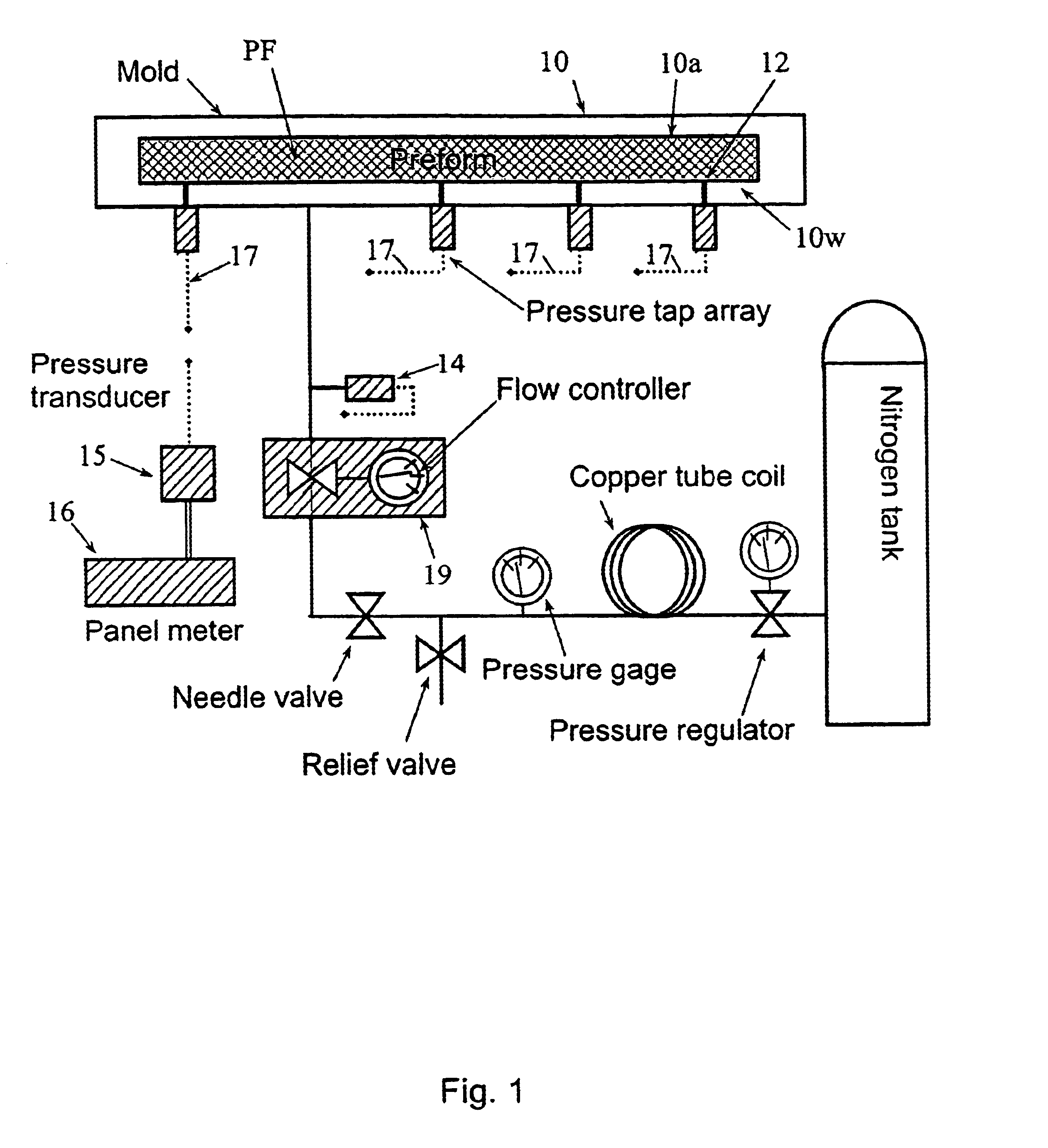
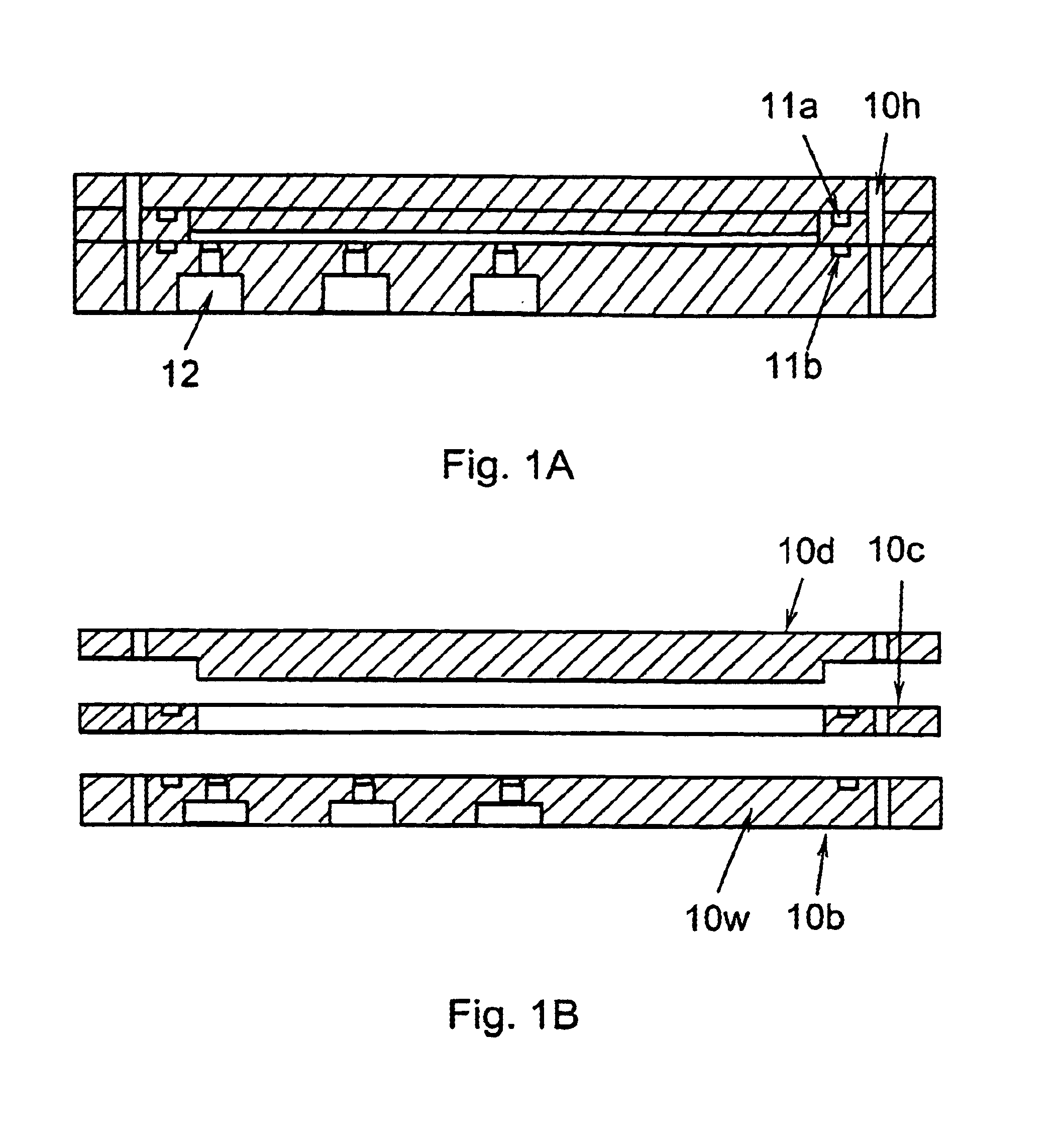
For purposes of illustration and not limitation, the invention will be described with respect to a simulated resin transfer mold 10 shown in FIGS. 1, 1A, and 1B. The simulated resin transfer mold 10 comprised a 229×279×3.17 mm aluminum mold wherein the corners of the rectangular-shaped mold cavity 10a were rounded with 12.7 mm radii. The mold comprised a bottom mold portion 10b, annular middle mold portion 10c, and upper mold portion 10d clamped together using conventional guide pins (not shown) received in aligned holes 10h and eight C-clamps (not shown) evenly spaced about the mold 10. O-ring seals 11a, 11b were disposed between the mold portions as shown in FIG. 1A. The wall 10w of the bottom portion 10a of the mold had twenty-five uniformly spaced 7.94 mm diameter ports 12. FIG. 2 shows a photograph of the bottom mold portion 10b. The middle mold portion 10c constitutes a frame with a cutout in the shape of the desired fiber preform PF to be received in the mold cavity 10a. The ...


PUM

PropertyMeasurementUnit
Fractionaaaaaaaaaa
Fractionaaaaaaaaaa
Frequencyaaaaaaaaaa

Abstract

Methods to detect and characterize a defect in a fiber preform residing in a molding cavity for liquid composite molding (e.g. resin transfer molding) to make a composite component or structure. The defect may result from fiber preform misplacement in the molding cavity, accidental inclusions, preform density variations, and / or distortion of the preform. Gas pressures at multiple locations on a mold wall are measured during gas flow through the mold cavity containing the fiber preform. Normalized or measured pressures are analyzed by discriminant analysis to detect and characterize any defect in the tested fiber preform.

Description

FIELD OF THE INVENTIONThe present invention relates to detection and characterization of defects in a fiber preform for use in the liquid molding method for making composite components or structures.BACKGROUND OF THE INVENTIONThe resin transfer molding (RTM) process has become a popular composite manufacturing process due to its suitability for high volume production and cost effectiveness [see references 1, 2]. In this process, the dry fiber reinforcement (preform) is enclosed in the mold and resin is injected and allowed to cure. Resin injection or transferability is defined by the permeability of the preform and it can be severely affected by defects, distortions or anomalies in the preform. In some cases, such as those involving complex geometries, it is not uncommon for the preform to be misplaced or shift and be distorted during mold closure. This fact, if not detected and corrected before resin injection, results in costly scrapping of the finished part [see reference 3]. Pre...

Claims


Application Information

Patent Timeline
IPC IPC(8): G01N15/08G01M99/00
CPCB29C70/48G01N15/0826B29C70/54
Inventor DANIEL, ISAAC M.KIM, SUN KYOUNGOPPERER, JEREMY G.
Owner NORTHWESTERN UNIV
Learn More