Valve gear of internal combustion engine

a technology of internal combustion engine and valve gear, which is applied in the direction of valve details, valve arrangements, valve drives, etc., can solve the problems of camshaft load increase, valve is liable to be jumped, and sliding portion wear is fastened, so as to enhance the durability of sliding portion

Inactive Publication Date: 2005-02-15
HONDA MOTOR CO LTD
View PDF11 Cites 28 Cited by
  • Summary
  • Abstract
  • Description
  • Claims
  • Application Information

AI Technical Summary

Benefits of technology

The present invention has been accomplished in view of the various problems associated with the above-described conventionally known system, and it is a first object of the present invention to provide a valve-operating system for an in

Problems solved by technology

It should be noted here that because the lifter spring is mounted between the valve and the subsidiary valve lifter, the following disadvantage is encountered: When the connecting means is in the non-connecting state, whereby the subsidiary cam provides the ineffective reciprocal motion to the subsidiary valve lifter by cooperation with the lifter spring, inertia forces of the subsidiary cam and the lifter spring are applied to the valve, whereby the valve is liable to be jumped.
However, if the preset load is set at the higher value, the following new problems arise: the load of a camshaft is increased; the wear of sliding

Method used


Image

  • Valve gear of internal combustion engine
  • Valve gear of internal combustion engine
  • Valve gear of internal combustion engine

Examples


second embodiment

the present invention shown in FIGS. 9 and 10 will be described below.

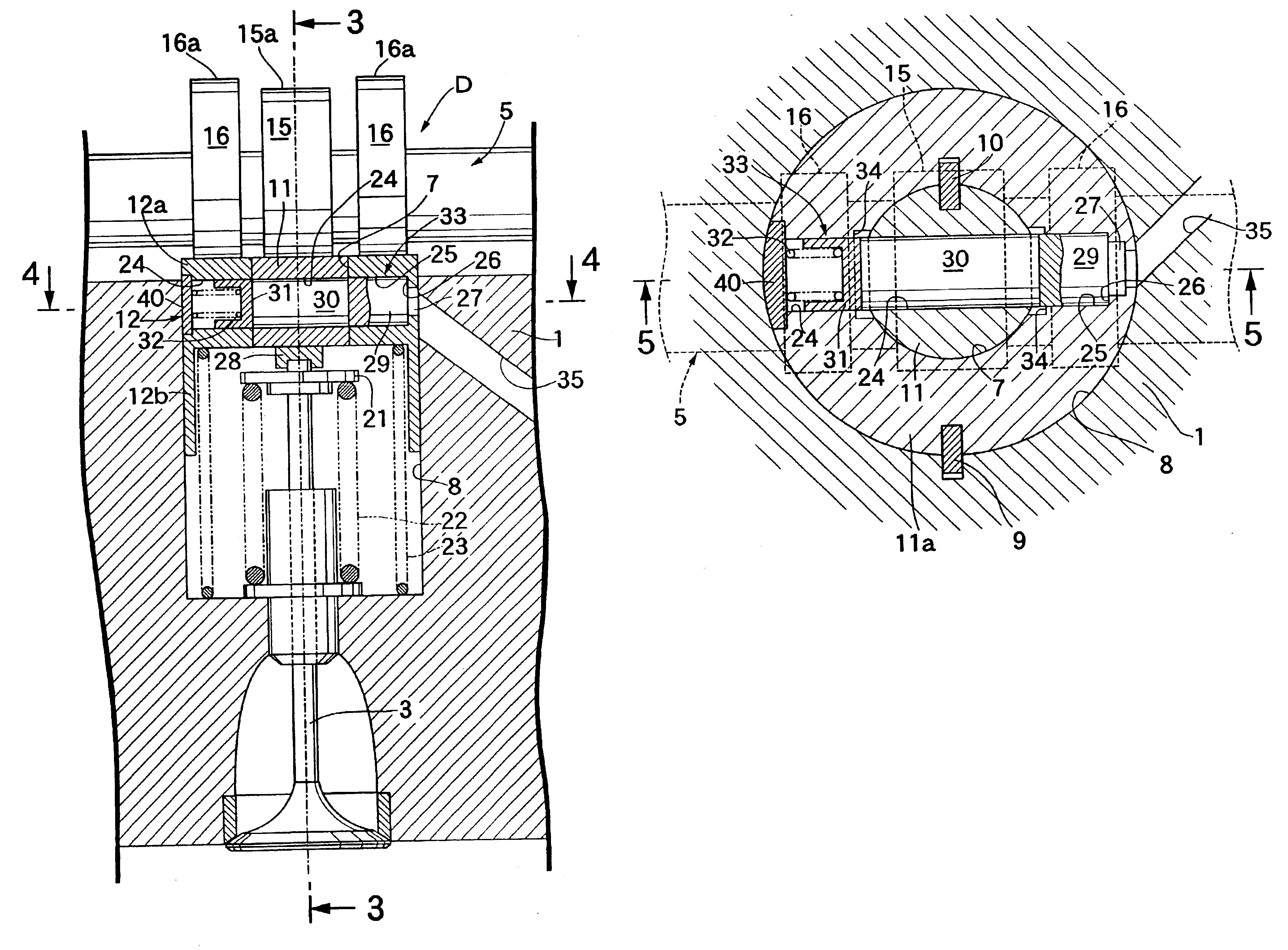
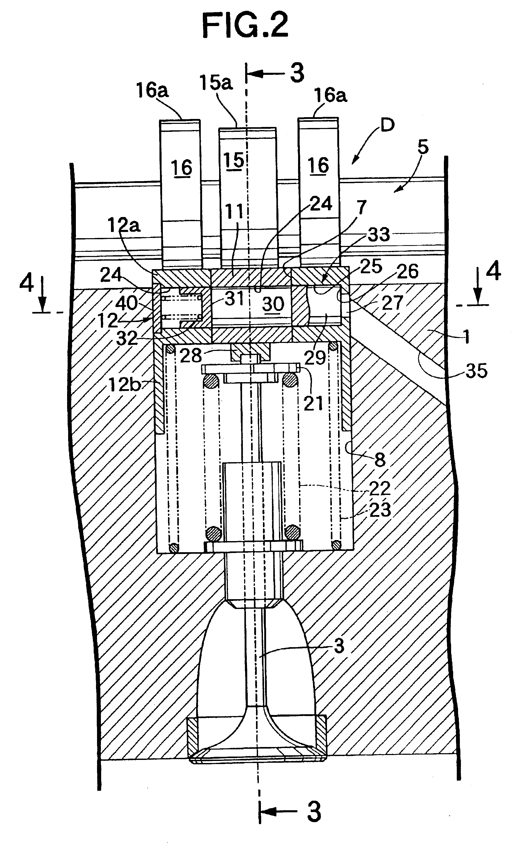
Flat abutment faces 60, 61; 60, 61 are formed on an inner peripheral surface of a subsidiary guide bore 25 in a subsidiary valve lifter 12 and opposite sides of an outer peripheral surface of a main valve lifter 11 received in the subsidiary guide bore 25, so that they are in abutment against each other for relative sliding movement. A main 24 and a subsidiary guide bore 25 are provided in the main and subsidiary valve lifters 11 and 12 to extend vertically through the abutment faces 60, 61; 60, 61.

With such arrangement, the following advantages are provided: Even if a relief recess 34 is not provided in the inner peripheral surface of the subsidiary valve lifter 12 as in the previously described embodiment, the interference of opposite ends of a connecting plunger 31 and a subsidiary valve lifter 12 can be avoided in a non-connecting state of a connecting means 33. In addition, even if a key 10 is not interposed ...

fourth embodiment

the present invention shown in FIGS. 18 and 19 will be described below.

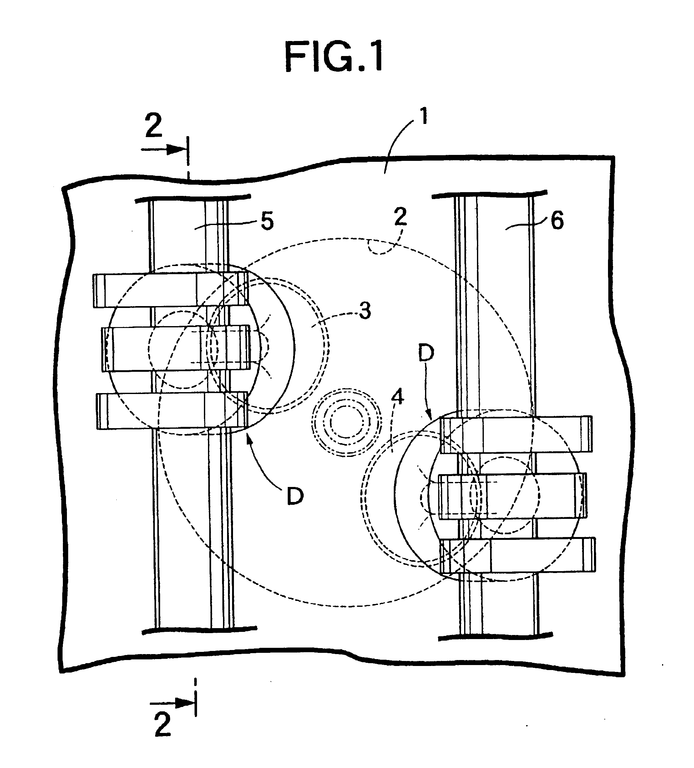
The forth embodiment of the present invention is applied to an four-valve type internal combustion engine including a pair of parallel intake valves 3, 3 and a pair of parallel exhaust valves (not shown). An intake camshaft 5 and an exhaust camshaft (not shown) are disposed immediately above the pair of intake valves 3, 3 and the pair of exhaust valves to extend in a direction of arrangement of the intake valves 3, 3 and in a direction of arrangement of the exhaust valves, respectively. Two sets of main and subsidiary valve lifters 11, 12; 11, 12 are mounted in correspondence to the pair of valves 3, 3. In this case, flat faces 46, 46 are formed on one-sides of outer peripheral surfaces of the main valve lifter 11, 11 of each pair, and the two sets of main and subsidiary valve lifters 11, 12; 11, 12 are disposed adjacent each other in such a manner that the flat faces 46, 46 are in abutment against each other. A ...

fifth embodiment

the present invention shown in FIGS. 11 and 12 will be described below.

In the fifth embodiment, left one 3′ of a pair of left and right intake valves 3′ and 3 is stopped in a low-speed operational range of the engine. In order to ensure that the left intake valve 3′ can be stopped, a left main cam 15′ has substantially no lift portion. However, in order to avoid the residence of a fuel in a corresponding intake port 1i′ during stoppage of the intake valve 3′, an extremely small-height lift portion may be formed on the main cam 15′, so that the intake valve 3′ can be opened at a very small opening degree in an intake stroke of the engine. A hydraulic pressure is supplied individually to left and right hydraulic pressure chambers 27′ and 27 through a pair of oil passages 35′ and 35, respectively.

The other constructions are the same as in the fourth embodiment and hence, portions or components corresponding to those in the fourth embodiment are designated by like reference characters i...


PUM


Abstract

A valve operating system for an internal combustion engine including a main valve lifter, a subsidiary valve lifter, a low-speed cam operating the main valve lifter, a high-speed cam operating the subsidiary valve lifter, a connecting device switched over between a non-connecting state in which the valve lifters are disconnected from each other, and a connecting state in which the valve lifters are connected to each other, a valve spring for biasing the valve in a closing direction, a lifter spring for biasing the subsidiary valve lifter toward the cam; thus, in a low-speed mode, that is non-connected states, an influence of a load of the lifter spring on the valve can be prevented, and in a high-speed mode, that is connected states, a sum total of loads of the valve spring and the lifter spring cap be applied to both of the valve lifters to improve the closing responsiveness of the valve.

Description

FIELD OF THE INVENTIONThe present invention relates to a valve-operating system for an internal combustion engine and particularly, to an improvement in a valve-operating system, including a main valve lifter moved in unison with valves mounted in an engine body, a subsidiary valve lifter adjoining the main valve lifter and slidable relative to the main valve lifter, a main cam for providing a first operational mode to the valve through the main valve lifter, a subsidiary cam capable of operating the subsidiary valve lifter with a lift amount larger than the main cam in a direction to open the valve, and a connecting means capable of being switched between a non-connecting state in which the individual movement of the main and subsidiary valve lifters is permitted, and a connecting state in which the main and subsidiary valve lifters are connected to each other and forced to be operated in unison with each other, so that when the main and subsidiary valve lifters are connected to ea...

Claims


Application Information

Patent Timeline
IPC IPC(8): F01L1/14F01L13/00
CPCF01L1/143F01L13/0015F01L13/0036F02B2275/18F01L2105/00F01L2107/00F01L2001/0537F01L2305/00F01L2307/00
Inventor HIRANO, MAKOTO
Owner HONDA MOTOR CO LTD
Why Eureka
Try Eureka