Self-camming snap ring for pop-up sprinkler with top serviceable diaphragm valve module

a technology of snap ring and diaphragm valve, which is applied in the field of sprinklers, can solve the problems of affecting the service life of the diaphragm valve, the diaphragm valve will fail, and the thin flexible diaphragm may also wear out, so as to facilitate the withdrawal of the snap ring, facilitate the removal of the valve module, and facilitate the repair or replacement.

Inactive Publication Date: 2005-02-15
HUNTER INDUSTRIES
View PDF4 Cites 61 Cited by
  • Summary
  • Abstract
  • Description
  • Claims
  • Application Information

AI Technical Summary

Benefits of technology

According to the present invention a self-camming snap ring is provided for removably securing a diaphragm valve module inside of a top serviceable pop-up sprinkler. The sprinkler includes an outer housing having an inlet at a lower end thereof. A riser is mounted inside the outer housing for vertical reciprocation through an opening in an upper end of the outer housing. A nozzle is mounted in an upper end of the riser for ejecting a stream of water. At least one valve actuator component is supported by the outer housing. The diaphragm valve module is mounted in the lower end of the outer housing for controlling the flow of water through the inlet in response to actuation of the valve actuator component. The diaphragm valve module is configured so that it is removable as a unit from the outer housing through the opening in the upper end of the outer housing upon removal of the riser from the outer housing. Thus, when the diaphragm valve fails, as is sometimes the case, the diaphragm valve module can be easily repaired or replaced after removing the riser, without having to dig up the sprinkler. The snap ring is mounted on top of the valve module. The snap ring is resilient and compressible and has a semi-circular shape including a pair of opposing peripheral annular portions. These annular portions can be disengaged from an annular groove formed in the interior wall of the outer housing by manually squeezing the annular portions together. The annular portions are formed with angled slots that receive pins that extend from the cover of the valve module to produce a camming movement that uniformly retracts the snap ring out of the annular groove to more readily permit removal of the valve module.
According to another aspect of the present invention, a snap ring is provided in the form of a semi-circular member made of a resilient flexible material. The member includes a pair of opposing peripheral annular portions that are radially retractable and expandable. Each opposing annular portion of the snap ring has a guide portion extending radially inwardly thereof. The guide portions of the snap ring have slots for receiving guide projections to control the radial retraction of the opposing annular portions to facilitate the withdrawal of the snap ring from a surrounding annular groove in an interior wall of an outer housing

Problems solved by technology

In many cases during the life of a so-called “valve-in-head” sprinkler the diaphragm valve will fail, often due to debris damaging the diaphragm valve seat or clogging the small passages in the diaphragm valve.
The thin flexible diaphragm may also wear out.
This is a relatively expensive, tedious and time consuming process.
Excavation of the defective sprinkler can also cause considerable damage to the surrounding landscaping.
However, impact type sprinklers are noisy, inaccurate in terms of arc coverage, and prone to breakage.
This part-by-part disassembly and re-assembly can be a difficult task for landscape maintenance personnel who are often simply gardeners.

Method used


Image

  • Self-camming snap ring for pop-up sprinkler with top serviceable diaphragm valve module
  • Self-camming snap ring for pop-up sprinkler with top serviceable diaphragm valve module
  • Self-camming snap ring for pop-up sprinkler with top serviceable diaphragm valve module

Examples


Embodiment Construction

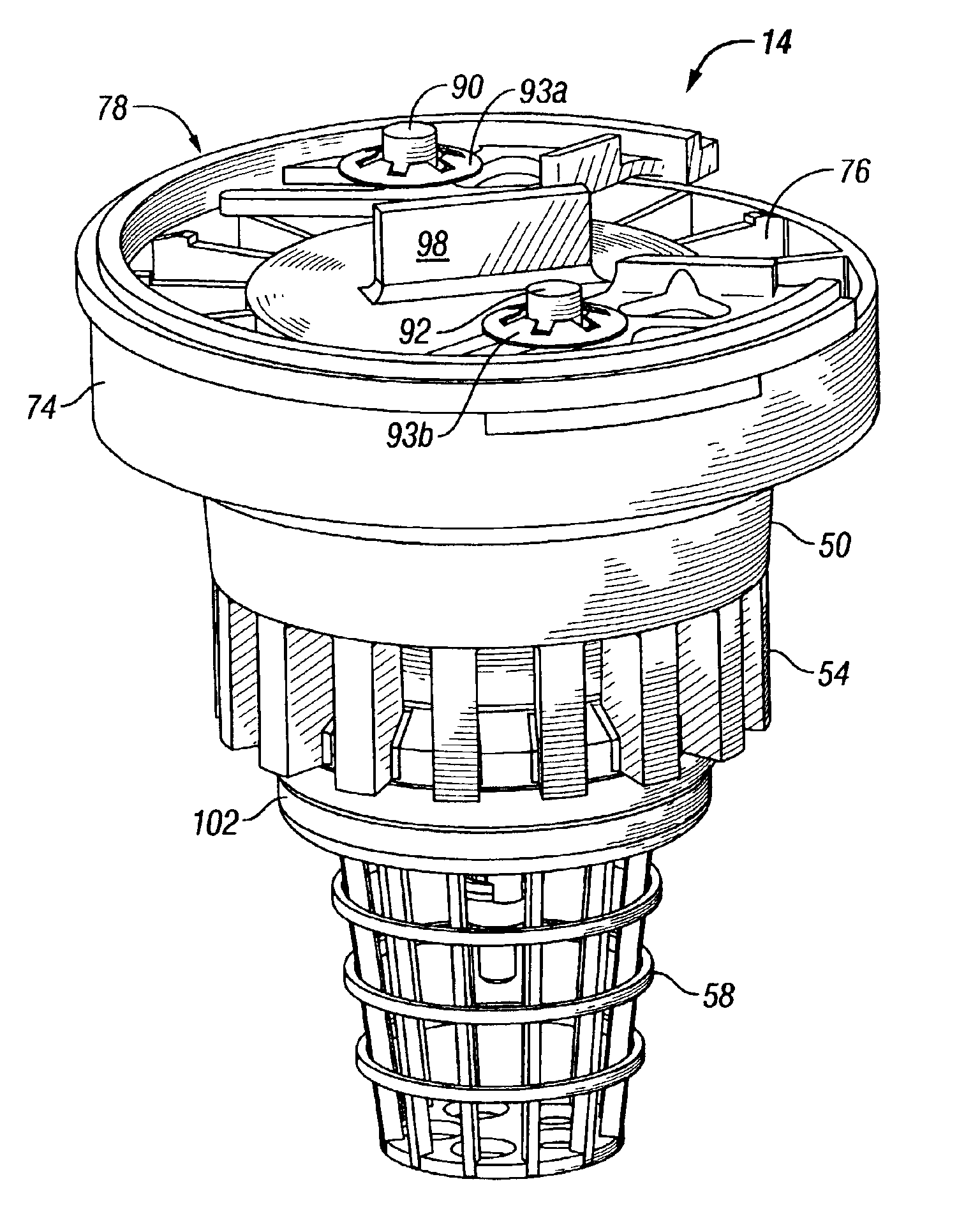
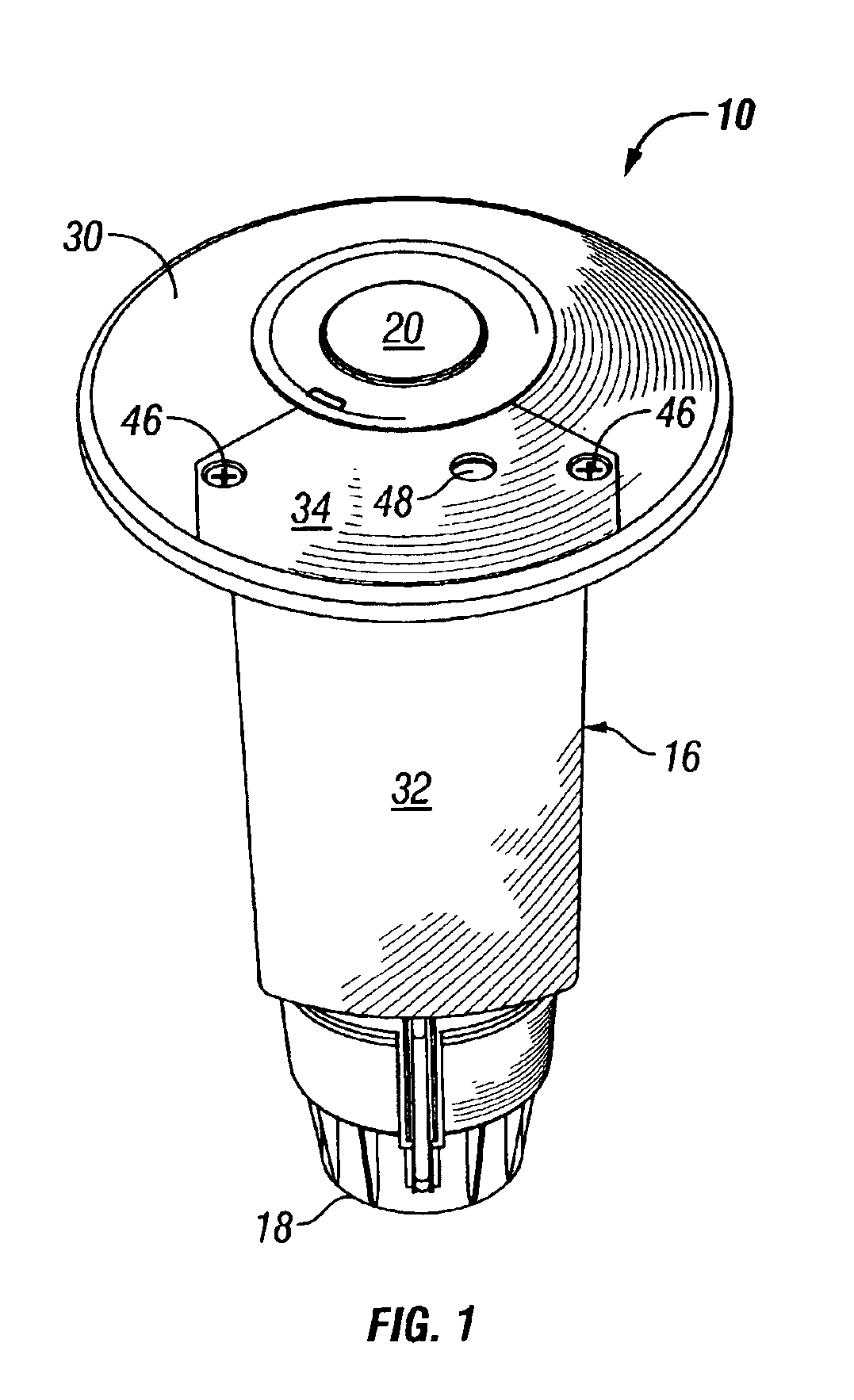
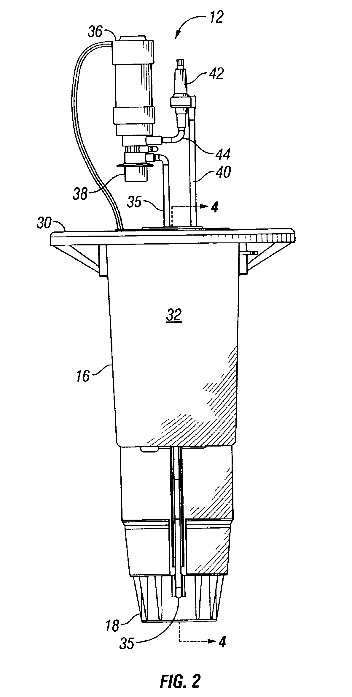
FIG. 1 illustrates a pop-up sprinkler 10 having a surface accessible valve actuator component assembly 12 (FIG. 2) and a top serviceable diaphragm valve module 14 (FIG. 5). Unless otherwise indicated, the parts of the sprinkler 10 are generally made of rigid molded plastic. The sprinkler 10 includes a vertically extending generally cylindrical hollow outer housing 16 (FIG. 1) having a female threaded inlet 18 at its lower end. As best seen in FIG. 4, the diaphragm valve module 14 is located in the lower end of the main housing 16 for admitting water through the inlet 18 into the interior of the housing 16. A tubular riser 20 is vertically reciprocable within the interior of the housing 16 when the housing 16 is connected to a source of pressurized water (not shown) and the diaphragm valve module 14 is opened and closed.

A cylindrical nozzle turret 22 (FIG. 4) including a conventional nozzle 22a is mounted at an upper end of the riser 20. The riser 20 is held in its retracted position...


PUM


Abstract

A diaphragm valve module is mounted in the lower end of the outer housing of a pop-up rotor type sprinkler for controlling the flow of water through an inlet in response to actuation of a valve actuator component. A resilient deformable semi-circular snap ring is mounted on top of the module and has a pair of opposing peripheral annular portions. Upon removal of the sprinkler riser, the snap ring can be disengaged from an annular groove formed in the interior wall of the outer housing by manually squeezing the annular portions together. This permits removal of the module for repair or replacement. The annular portions of the snap ring are formed with angled slots that receive projections that extend from the cover of the module to produce a camming movement that uniformly retracts the snap ring out of the annular groove to more readily permit removal of the module.

Description

BACKGROUND OF THE INVENTIONThe present invention relates to sprinklers used to irrigate lawns, playing fields, golf courses and the like, and more particularly, to an irrigation sprinkler that can be serviced from the top of the sprinkler without having to excavate the same.Sprinklers have long been used to water turf and other vegetation. Many designs have been developed with the goal of uniformly distributing a desired precipitation rate over a given area. One of the most common type of sprinklers is the pop-up type that is normally mounted in a sub-surface location so that the top of the sprinkler is substantially at ground level. When water pressure is applied, a riser with a nozzle at its upper end extends and delivers a spray of water over the adjacent area. When the water pressure is terminated, a spring retracts the riser so that the upper end of the nozzle is flush with the head of the sprinkler. This removes the sprinkler as an obstacle to play occurring on the turf and al...

Claims


Application Information

Patent Timeline
Patent Type & Authority Patents(United States)
IPC IPC(8): B05B3/04B05B3/02B05B15/00B05B15/10B05B15/06
CPCB05B3/0422B05B15/10B05B15/008B05B15/065B05B15/40B05B15/65B05B15/74
Inventor SMITH, PHILLIP E.
Owner HUNTER INDUSTRIES
Why Eureka
Try Eureka