This helps you quickly interpret patents by identifying the three key elements:
Problems solved by technology
Method used
Benefits of technology
Benefits of technology
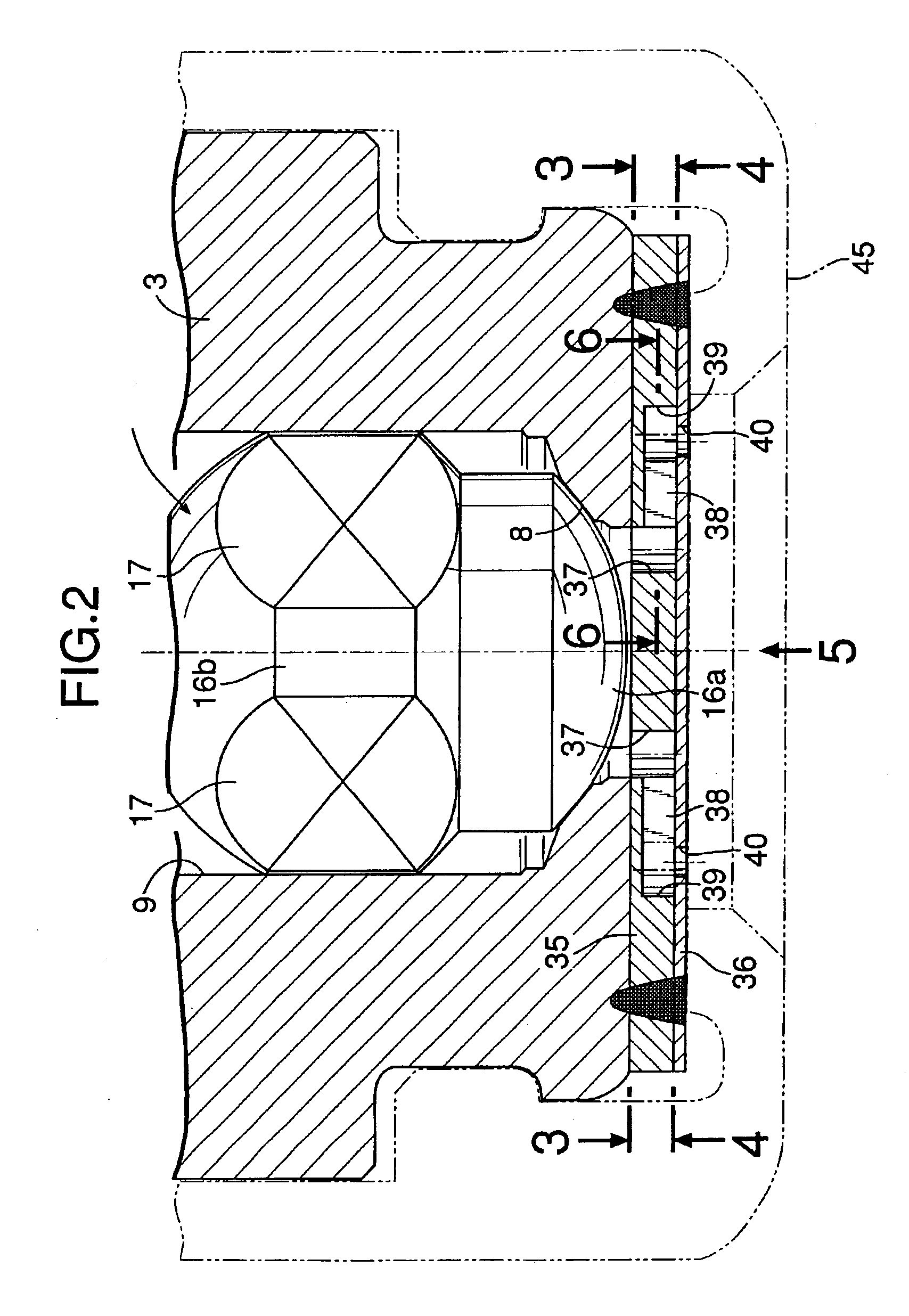
With the first feature, the fuel injected from plurality of the swirling chambers into the corresponding fuel injection orifices during opening of the fuel injection valve forms a plurality of hollow conical fuel spray forms under the action of an injection pressure and a centrifugal force, and liquid membrane portions of the adjoining fuel spray forms collide with one another, whereby the atomization of the fuel can be effectively promoted. Moreover, a single coalesced fuel spray form having a fuel density higher in a central zone and lower in an outer peripheral zone is formed finally and drawn into an engine along with intake air, while possibly preventing the fuel from being deposited on an inner wall of an intake passage to the engine. This can greatly contribute to an enhancement in startability of the engine and an improvement in mileage.
With the twenty third feature, the side holes, the swirling chambers and the fuel injection orifices can be provided in a larger number, which is advantageous for a specification of a large fuel flow amount.
Problems solved by technology
However, the conventional fuel injection valve has the following disadvantage: conical fuel spray forms formed by the fuel injected from the fuel injection orifices are directed in predetermined directions without interfering with one another, so that the fuel particle density of the each of the fuel spray forms tends to be lower in a central zone of the foam and higher in an outer peripheral zone of the foam, whereby a large amount of fuel is deposited to an inner wall of an intake passage to an engine.
Method used
Image
Click on the blue label to locate the original text in one second.
Reading with bidirectional positioning of images and text.
Examples
second embodiment
the present invention shown in FIG. 8 will now be described.
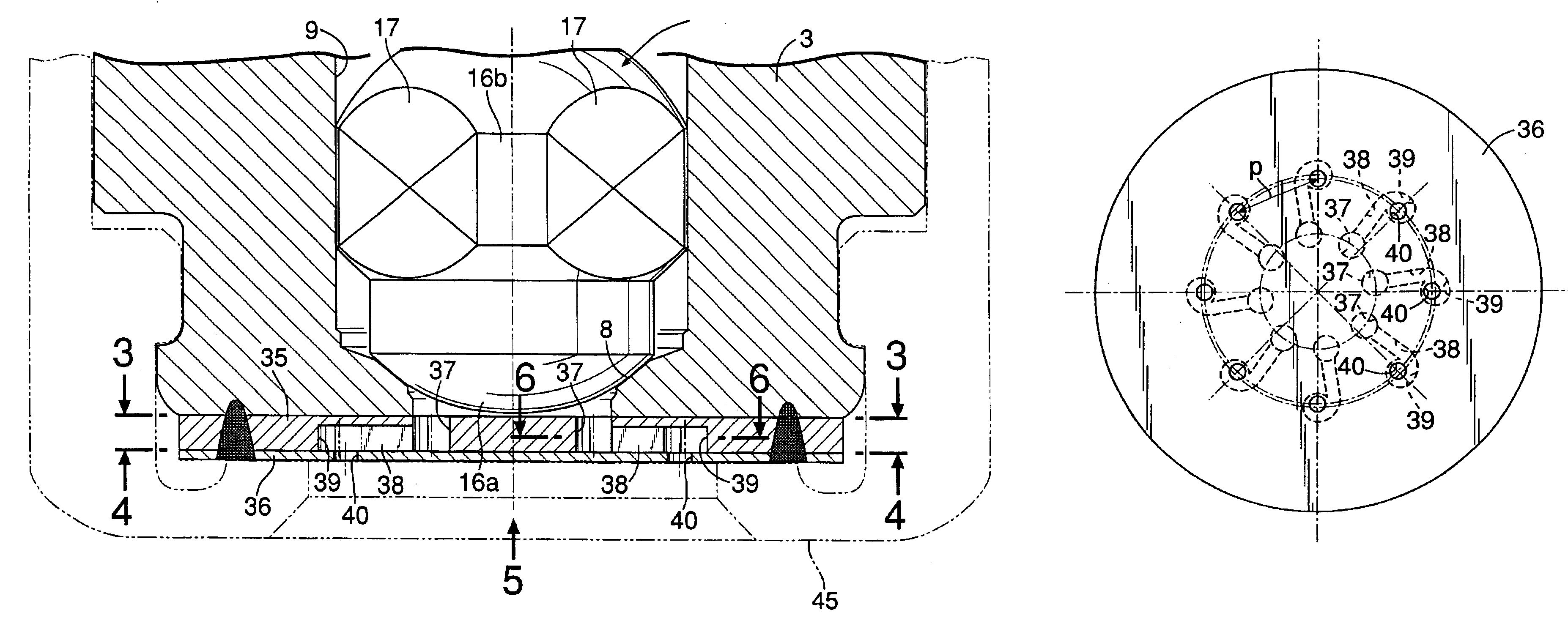
The second embodiment has the same arrangement as that in the first embodiment, except that a large number of side holes 37 are disposed in a zigzag manner on two concentric pitch circles C1 and C2, and accordingly a large number of swirling chambers 39 are disposed in a zigzag manner on two pitch circles C3 and C4 larger in diameter than and concentric with the pitch circles C1 and C2. Therefore, portions or components corresponding to those in the previous embodiment are designated by the same reference numerals and symbols in FIG. 8, and the description of them is omitted.
According to the second embodiment, the side holes 37, the swirling chambers 39 and the fuel injection orifices 40 can be provided in a larger number, which is advantageous for a specification of a larger fuel flow amount.
third embodiment
the present invention shown in FIG. 9 will now be described.
In the third embodiment, a plurality of swirling chambers 39 are arranged annularly on a pitch circle concentric with and smaller than a pitch circle of the group of side holes 37 arranged annularly. Each of transverse conduits 38 is inclined at an angle α with respect to a radius line L1 of a valve seat 8 passing through the center of the corresponding side hole 37, and the angular positions of the corresponding side hole 37 and the corresponding swirling chamber 39 with respect to the center of the valve seat 8 are displaced from each other. The arrangement of the other components is the same as that in the first embodiment, and hence portions or components corresponding to those in the first embodiment are designated by the same reference numerals and symbols in FIG. 9.
According to the third embodiment, the swirling chambers 39 and fuel injection orifices 40 cannot be provided very in a very large number, but the size of...
fourth embodiment
the present invention shown in FIGS. 10 and 11 will now be described.
The fourth embodiment has the same arrangement as that in the first embodiment, except that a circular dispensing chamber 50 is defined in the intimidate plate 35 to lead to a downstream end edge of a valve seat 8, and a large number of transverse conduits 38 are extended radially from an outer periphery of the dispensing chamber 50 to reach a large number of swirling chambers 39. Therefore, portions or components corresponding to those in the first embodiment are designated by the same reference numerals and symbols in FIGS. 10 and 11, and the description of them is omitted.
According to the fourth embodiment, the fuel is dispensed from the common dispensing chamber 50 into the large number of transverse conduits 38, and hence a large number of side holes 37 as in the first embodiment are not required, which can contribute to the simplification of a structure. However, the volume of the common dispensing chamber 50...
PUM
Abstract
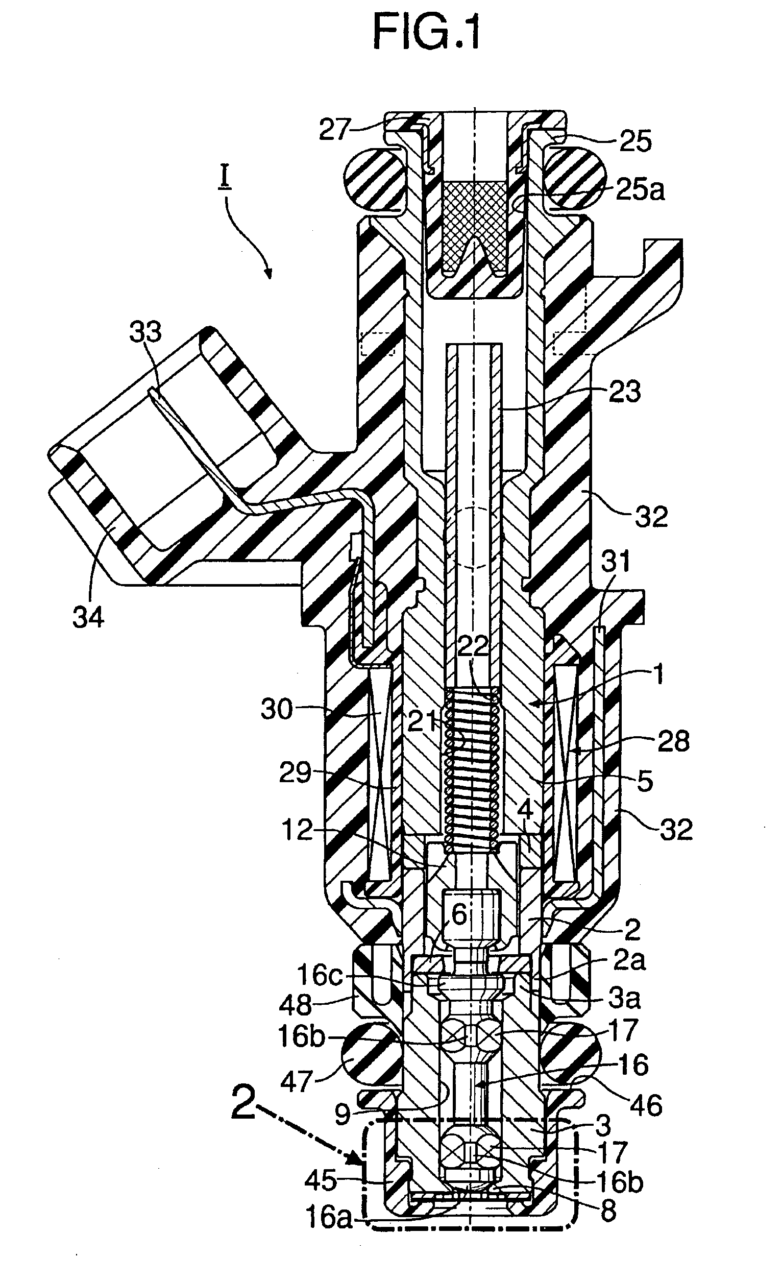
A fuel injection valve includes a valve seat member, and an injector plate which is coupled to a front end face of the valve seat member and has a plurality of fuel injection orifices disposed about an axis of the valve seat member to communicate with a valve seat. Swirling means for swirling a fuel injected from each of the fuel injection orifices is provided in at least one of the valve seat member and the injector plate. The plurality of fuel injection orifices are disposed so that liquid membrane portions of adjoining hollow conical fuel spray forms formed by the fuel injected from the fuel injection orifices collide with one another. Thus, the atomization of the injected fuel can be further promoted, and a coalesced fuel spray form having a fuel particle density higher in a central zone and lower in an outer peripheral zone can be formed.
Description
BACKGROUND OF THE INVENTION1. Field of the InventionThe present invention relates to a fuel injection valve used mainly in a fuel-supplying system for an internal combustion engine, and particularly to an improvement in a fuel injection valve comprising a valve member, a valve seat member into a front end face of which a downstream end of a valve seat cooperating with the valve member opens, an injector plate coupled to the front end face of the valve seat member and having a plurality of fuel injection orifices which are disposed about an axis of the valve seat to communicate with the valve seat, in which a swirling means is provided in at least one of the valve seat member and the injector plate for swirling a fuel injected from each of the fuel injection orifices.2. Description of the Related ArtA conventional fuel injection valve is already known, as disclosed, for example, in Japanese Patent No. 2659789.The conventional fuel injection valve is designed to swirl a fuel injected ...
Claims
Application Information
Patent Timeline
Application Date:The date an application was filed.
Publication Date:The date a patent or application was officially published.
First Publication Date:The earliest publication date of a patent with the same application number.
Issue Date:Publication date of the patent grant document.
PCT Entry Date:The Entry date of PCT National Phase.
Estimated Expiry Date:The statutory expiry date of a patent right according to the Patent Law, and it is the longest term of protection that the patent right can achieve without the termination of the patent right due to other reasons(Term extension factor has been taken into account ).
Invalid Date:Actual expiry date is based on effective date or publication date of legal transaction data of invalid patent.

