In situ load sharing brush seals

a brush seal and load-sharing technology, applied in the field of rotating seals, can solve the problems of excessive leakage, plastic deformation or fatigue failure, and the ability to seal very high differential pressures in excess of 400 psid is again limited to substantially less than twice the 400 psid limit, and additional series brush seals in excess of two have no practical capacity of sealing, so as to ensure rotational stability

Inactive Publication Date: 2005-02-15
GENERAL ELECTRIC CO
View PDF14 Cites 28 Cited by
  • Summary
  • Abstract
  • Description
  • Claims
  • Application Information

AI Technical Summary

Benefits of technology

A particular advantage of the present invention is that the two brush seals 20,22 may have substantially identical or common designs except for a single design feature thereof having different configurations for sharing the pressure loading with blowdown, with preferably equal load sharing. The method illustrated in FIG. 3 begins with the definition of each brush seal with substantially identical design features and configurations thereof, including size and dimension and material properties. Each brush seal includes its pack of bristles mounted between the corresponding forward and aft plates, with the various geometric dimensions A,B,C and E. And, the two seals are axially spaced apart by the dimension D.

Problems solved by technology

Large turbines also have correspondingly large pressure drops of the fluid flow therethrough which requires suitable sealing during operation.
Over-pressurization of the brush seal will cause excessive leakage, plastic deformation thereof or fatigue failure in short time.
Brush seals may be disposed in series, but again experience has shown that their ability to seal very high differential pressures in excess of 400 psid is again limited to substantially less than twice the 400 psid limit, correspondingly reduced by the safety factor, for each seal in view of the practical variation in load sharing therebetween.
And, experience has additionally shown that additional series brush seals in excess of two have no practical capability of sealing increased differential pressure imposed across those multiple stage brush seals.
Accordingly, the sealing capability of the multistage brush seals is limited by that last stage, and correspondingly limits the maximum differential pressure which the seals may safely carry during operation.
However, the specific value of the seal clearance affects the total sealing capability, with larger clearances decreasing loading capability, while smaller clearances increase loading capability.
However, small clearances subject the bristles to increased friction rubbing with the land during transient operation of the engine, with friction rubbing correspondingly heating the components.
Friction rubbing of the bristles with the shaft causes local heating thereof and corresponding thermal expansion which can adversely affect stability of the rotating shaft.
And, the shaft is subject to undesirable instability, such as wobbling, which can require emergency shut down of the entire engine.
Soft or flexible bristles are subject to increased bending under differential pressure, and hard or stiff bristles increase the friction heating under rubbing with the land.
Furthermore, the differential pressure exerted across the pack of bristles effects blowdown therein in which the inclined bristles deflect slightly radially inwardly, which correspondingly increases friction heating during rubbing with the land.
And, the ability to achieve load sharing between the multiple seals stages is limited by bristle rubbing and rotor stability.

Method used


Image

  • In situ load sharing brush seals
  • In situ load sharing brush seals
  • In situ load sharing brush seals

Examples


Embodiment Construction

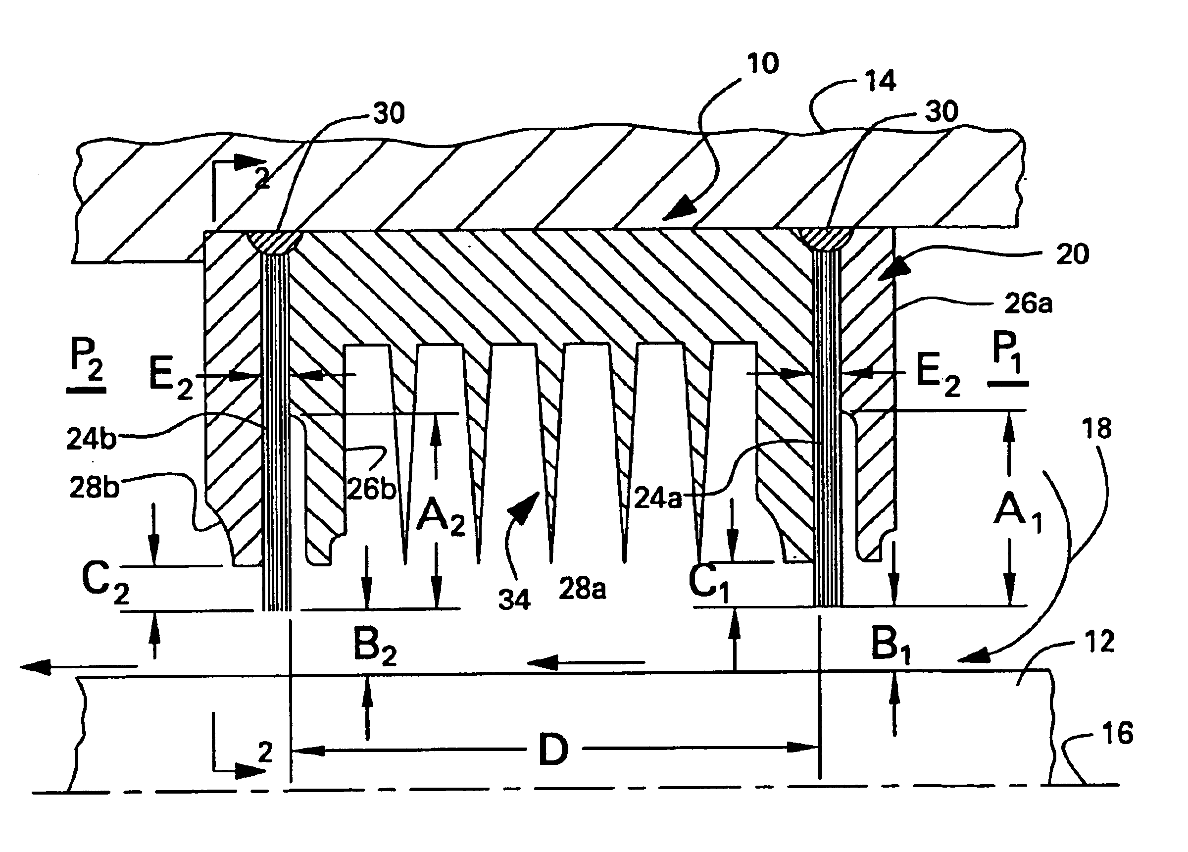
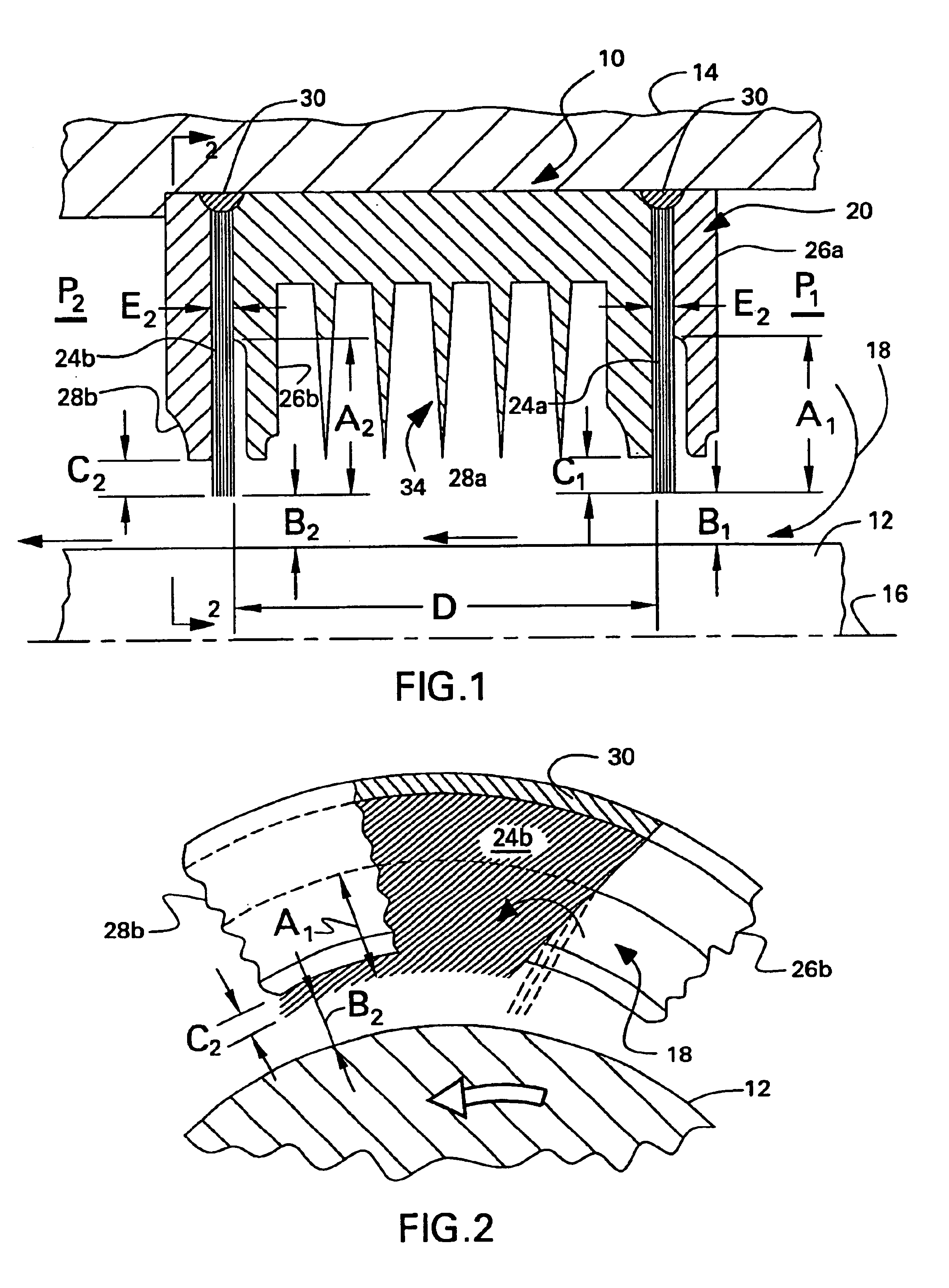
Illustrated in cross section in FIG. 1 is a multistage annular seal 10 disposed concentrically around an annular land 12 in the exemplary form of a rotor shaft. The seal is suitably mounted in an annular seal support 14 coaxially about an axial or longitudinal centerline axis 16 of the rotor shaft.

The seal is configured in FIG. 1 for use in large industrial gas or steam turbine engines, with the seal being a stationary or stator component surrounding the rotating shaft. Alternatively, the land 12 may be stationary, with the seal being mounted for rotary movement relative thereto.

In either configuration, the seal and land experience relative rotation during operation in the engine, and the seal is configured for sealing differential pressure maintained on opposite axial sides of the seal. For example, a fluid 18, such as steam, is maintained on the right side of the seal at a high pressure P1 and is effectively sealed by the multistage seal for minimizing leakage between the seal and...


PUM


Abstract

Multistage brush seals are made by initially specifying designs thereof for collectively sharing a differential pressure along an adjacent land subject to relative rotation with the seals. The seals are modified to share the loading without blowdown therefrom. The seals are further modified to ensure rotational stability with the land. The seals are built and tested under pressure to determine pressure blowdown thereof. And then, the seals are again modified to share the pressure loading under blowdown. In this way, the seals share the load in situ under the effects of blowdown.

Description

BACKGROUND OF THE INVENTIONThe present invention relates generally to rotating seals, and, more specifically, to multistage brush seals.Various forms of engines or motors include various forms of seals therein specifically configured for separating relatively high and low pressure regions thereof. For example, gas and steam turbine engines have various stages therein in which air, combustion gases, and steam travel downstream with changes of pressure and temperature thereof.Turbine engines are made as large as practical for maximizing output work and performance efficiency. Large turbines also have correspondingly large pressure drops of the fluid flow therethrough which requires suitable sealing during operation.In a labyrinth seal, a row of annular seal teeth is disposed closely adjacent to a cooperating land for relative rotation therewith, with a radial clearance therebetween for reducing the likelihood of undesirable rubbing therebetween. Another form of seal typically found in...

Claims


Application Information

Patent Timeline
Patent Type & Authority Patents(United States)
IPC IPC(8): F01D11/00F01D11/02F16J15/00F16J15/22F16J15/32G06F17/50
CPCF01D11/02F16J15/3288F16J15/006F05D2240/56
Inventor SARSHAR, HAMID REZATURNQUIST, NORMAN ARNOLDDINC, OSMAN SAIM
Owner GENERAL ELECTRIC CO
Why Eureka
Try Eureka