Chain

a technology of chain and chain, applied in the field of chains, can solve the problems of chain snakes, time-consuming grinding process, and substantial increase in the cost of equipment which utilizes chains, and achieve the effects of reducing weight, simplifying chain guidance, and superior thrust load performan

Inactive Publication Date: 2005-02-15
TSUBAKIMOTO CHAIN CO
View PDF17 Cites 25 Cited by
  • Summary
  • Abstract
  • Description
  • Claims
  • Application Information

AI Technical Summary

Benefits of technology

It is, accordingly, a general object of the invention to provide a chain provided with a plurality of rolling members between a roller and a bushing, or between a roller and a pin, which exhibits one or more of the following advantages: superior thrust load performance and reduced weight; simplified guidance of the chain on a rail or the like; reduced roller wear occurring when the chain meshes with a sprocket; capability of carrying an unlimited variety of materials or attachments; and smooth and reliable rotation of the rollers.
Thus, according to the invention, thrust bearing plates, which may be simple plates or parts of substantially ring-shaped holders, are arranged between the inside surfaces of the inner link plates and the end surfaces of the roller. When a thrust load is applied to the roller during the rotation of the roller, the thrust load is received by the inner link plate through the thrust bearing plate. Since the thrust bearing plate which receives a thrust load has a wide area for receiving the thrust load, superior thrust load performance is achieved.
Moreover, since the outer diameter of the roller is smaller than the widths of the inner and outer link plates, a rail can be arranged between the opposite inner link plates, so that guidance of the chain is simplified. Further, since the roller does not protrude beyond the inner and outer link plates, it cannot interfere with material or attachments carried by the chain. Miniaturization of the roller also achieves a weight reduction, and wear of the roller, when it meshes with a sprocket, is reduced.
When the rolling members are composed of crowning rolling members and relief end rolling members, stress concentration, which is generated at both ends of each rolling member is relieved, smoother rotation of the roller is ensured, and thrust and radial load performance is improved.

Problems solved by technology

A second problem with the chain shown in FIG. 17 is that, because the outer diameter of the roller 5 is larger than the widths of the inner link plates 2 and the outer link plates 6, when the roller 5 travels only on a rail R1 as shown in FIG. 1B, the chain is likely to snake.
However, the time and effort required to provide the rail R2 with a recess leads to substantial increase in the cost of the equipment which utilizes the chain.
A third problem is that the formation of the integral inwardly extending collar 5a on the roller 5 requires the cutting or grinding of a recess portion 5b in the interior of the roller.
The cutting or grinding process is time-consuming and difficult, resulting in low productivity and increased cost.
A fourth problem is that, since the outer diameter of the roller 5 is large, shock and wear are likely to occur as the chain meshes with a sprocket.
A fifth problem is that attachments and conveyed materials can interfere with a portion of the roller 5 projecting beyond the inner link plates 2 and the outer link plates 6.
A sixth problem is that, although the rolling members 4 are arranged between the bushing 3 and the roller 5, an axial thrust load applied to the roller 5, results in skew of the rolling members 4 (that is, tilting of the rolling members 4 with respective to their proper axes of rotation).
A second problem with the chain of FIG. 20 is that heat generated due to the sliding contact between the roller 15 and the bushing 13 can exercise an adverse effect on material carried by the chain.
A third problem is that there is a relatively high coefficient of friction between the roller 15 and the bushing 13 because of their sliding contact, and consequently more power is required to move the chain.
A fourth problem is that, when a thrust load is applied to the chain 11, an end surface of the roller 15 slides against an inside surface of one of the inner link plates 12, generating wear, which reduces the thickness of the link plate 12 and reduces its breaking strength.
First, when a thrust load is applied to the chain 21, an end surface of the roller 25 slides against an inside surface of one of the inner link plates 22, generating a large amount of wear.
Consequently the breaking strength of the inner link plates 22 is decreased and their breakage can result in failure of the chain.
Secondly, when a thrust load is applied to the chain, a ball 24c, which is on an end of a rolling member 24b, is loaded heavily, and the increased stress applied to the ball 24c causes rapid wear.
A third problem with the chain of FIG. 21 is that, because each rolling body 24 comprises not only a rolling member 24b, but also two balls 24c arranged at opposite ends of the roller member, 24b rolling member 24b, the component count in the chain is high, which results in high manufacturing cost and difficult assembly.

Method used


Image

  • Chain
  • Chain
  • Chain

Examples


first embodiment

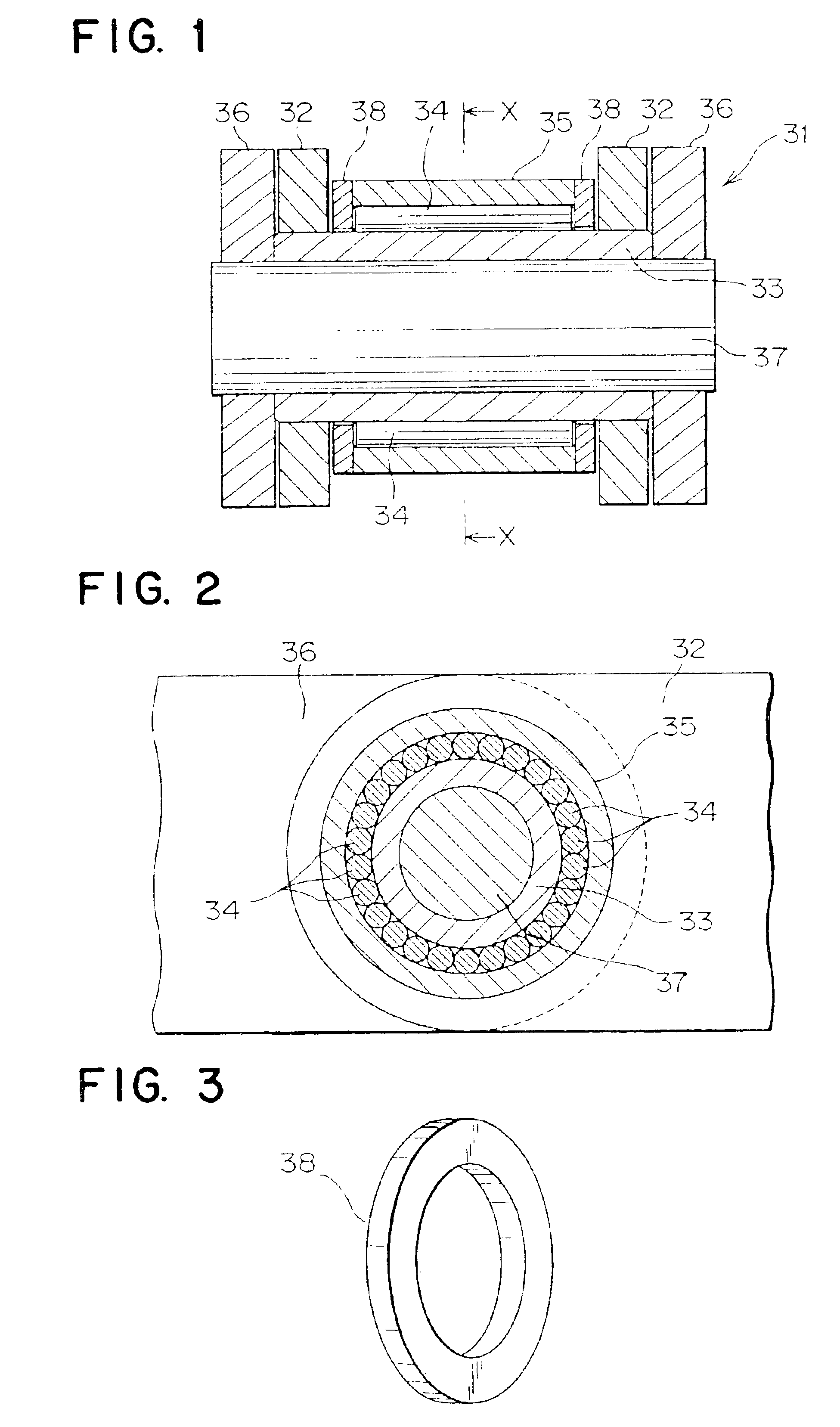
the invention will be described with reference to FIGS. 1, 2 and 3.

In a chain 31 shown in FIG. 1, two inner link plates 32, spaced from, and in parallel relationship to, each other, are connected by a hollow, cylindrical bushing 33. A plurality of rolling members 34 is arranged on the outer circumferential surface of the bushing 33, and a cylindrical roller 35, disposed between the pair of inner link plates 32, surrounds the rolling members 34. As shown in FIG. 2, the rolling members 34 are arranged next to one another, without a holder. Two outer link plates 36 are arranged on the outsides of the pair of inner link plates 32, in spaced, parallel relationship to each other. The outer link plates 36 are connected to each other by a pin 37, which extends through the bushing 33. The inner and outer link plates on each side extend in the longitudinal direction of the chain, and overlap one another as in a conventional roller chain.

As shown in FIG. 1, thrust bearing plates 38 are arrange...

second embodiment

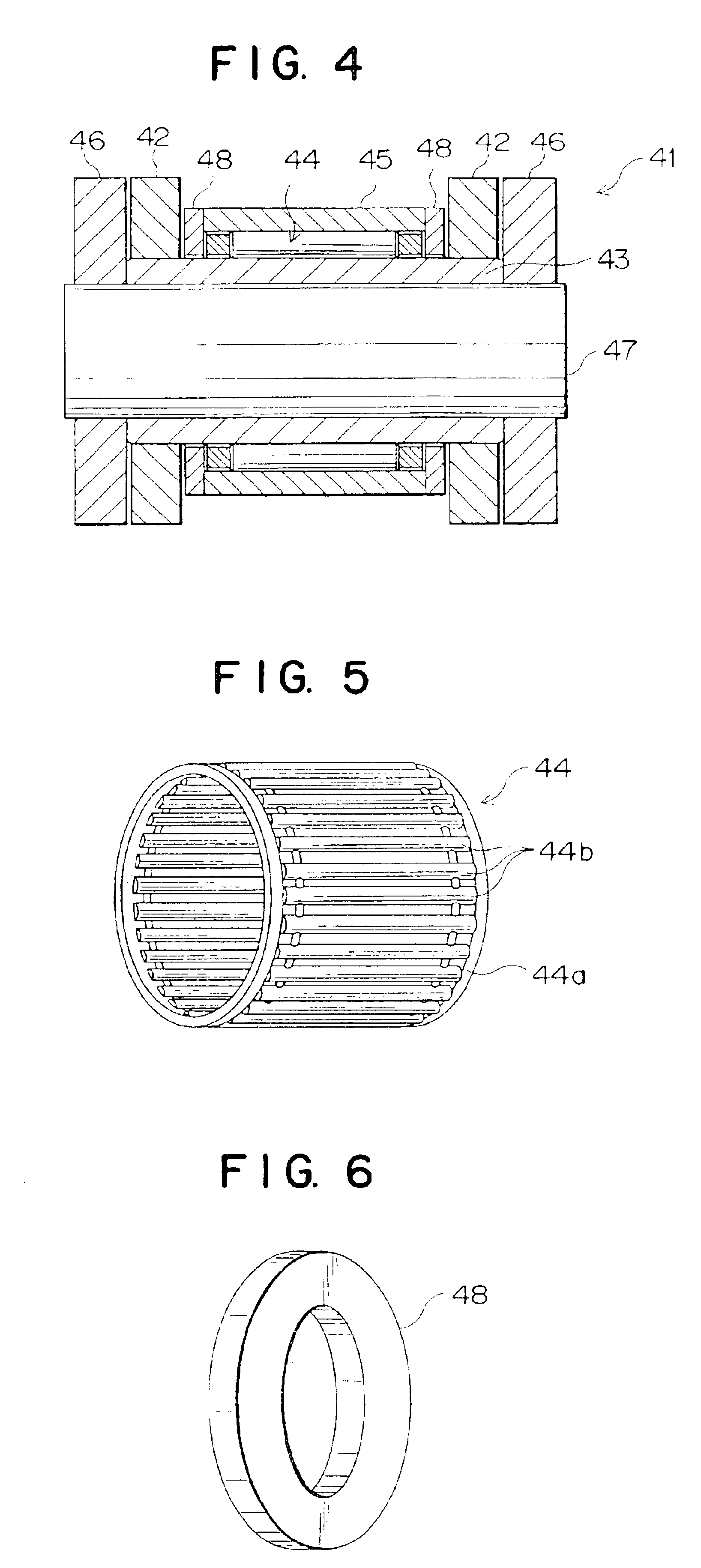
the invention will now be described with reference to FIGS. 4, 5 and 6.

In a chain 41 shown in FIG. 4, two inner link plates 42, spaced, and in parallel relationship to each other, are connected to each other by a hollow, cylindrical bushing 43. Rolling members 44, with a holder, are arranged on the outer circumferential surface of the bushing 43, and a cylindrical roller 45, surrounding the rolling members 44 with the holder, is disposed between the inner link plates 42. As shown in FIG. 5, the structure between the bushing 43 and the roller is composed of a cylindrical holder 44a and a plurality of rolling members 44b. The rolling members 44b are rotatably held in window holes in the holder 44a. A pair of outer link plates 46, in spaced, parallel relationship to each other, are arranged on the outsides of the inner link plates 42. The outer link plates 46 are connected to each other by a pin 47, which extends through the bushing 43.

As shown in FIG. 4, thrust bearing plates 48 are a...

third embodiment

the invention will be described with reference to FIGS. 7, 8 and 9.

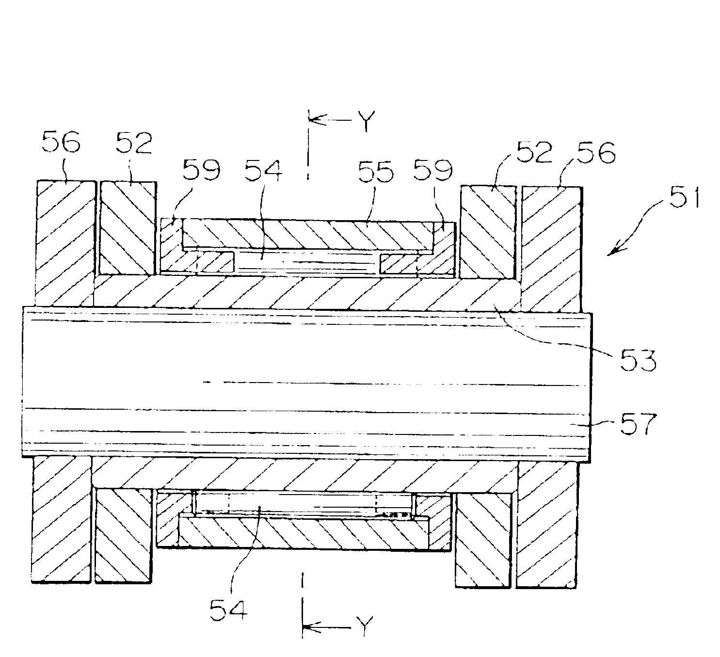
In the chain 51 shown in FIG. 7, inner link plates 52, spaced from each other, and in parallel relationship to each other, are connected by a hollow, cylindrical bushing 53. A plurality of rolling members 54 is arranged on the outer circumferential surface of the bushing 53, and a cylindrical roller 55, surrounding the plurality of rolling members 54, is disposed between the pair of the inner link plates 52, As shown in FIGS. 7 and 8, each of the rolling members 54 is held rotatably by a substantially ring-shaped holder 59. Outer link plates 56, in spaced, parallel relationship to each other are arranged on the outsides of the pair of inner link plates 52. The outer link plates 56 are connected to each other by a pin 57, which extends through bushing 53.

Substantially ring-shaped holders 59 are arranged between the inside surfaces of the pair of inner link plates 52 at both ends of the roller 55. As shown in FIGS. 9(A...


PUM


Abstract

A roller chain incorporates a plurality of rolling members between a roller and a bushing. A thrust bearing plate is provided between the end surfaces of the roller and inside surfaces of inner link plates. The outer diameter of the roller is smaller than the widths of the inner link plates and the outer link plates and the roller is accomodated in a projected area of the widths of the inner link plates and the outer link plates.

Description

FIELD OF THE INVENTIONThis invention relates to a chain incorporating a plurality of rolling members between a roller and a bushing, or between a roller and a pin.BACKGROUND OF THE INVENTIONFIG. 17 is a cross-sectional view of a chain incorporating rolling members , disclosed in Japanese Laid-open Patent Publication No. Sho. 62-4122 (Japanese Examined Patent Publication No. Hei. 4-78523).The chain 1, shown in FIG. 17, includes a pair of inner link plates 2 spaced from each other in parallel relationship, and connected to a hollow, cylindrical bushing 3. Rolling members 4 are arranged on the outer circumferential surface of the bushing 3, and a roller 5, disposed between the inner link plates 2 surrounds the rolling members 4. Inwardly projecting collars 5a are integrally formed on the ends of the roller 5.A recess portion 5b, for accommodating the rolling members 4, is formed between the inwardly projecting collars 5a. The collars 5a hold and guide the rolling members 4. A pair of o...

Claims


Application Information

Patent Timeline
Patent Type & Authority Patents(United States)
IPC IPC(8): F16G13/00F16G13/06B65G39/20B65G17/38F16C17/04F16C19/26F16C33/34
CPCF16G13/06F16C21/00B65G39/20
Inventor KANEHIRA, MAKOTOSAJI, TOMOYUKI
Owner TSUBAKIMOTO CHAIN CO
Why Eureka
Try Eureka