Electric generator and motor drive system

a technology of motor drive and electric generator, which is applied in the direction of electric generator control, electric devices, machines/engines, etc., can solve the problems of increasing the load on the drive, increasing the charging time, and many tasks that cannot be completed withou

Inactive Publication Date: 2005-02-15
BRANDON DENNIS +1
View PDF52 Cites 77 Cited by
  • Summary
  • Abstract
  • Description
  • Claims
  • Application Information

AI Technical Summary

Benefits of technology

A two-motor drive is also described with a motor mounted on both the left side and the right side of the generator with a gearbox mounted to the face of each motor opposite the face mounted to the generator. The output shaft of each gearbox is the axle for the wheel on each side of the mower. A metal plate is mounted to the bottom of the assembly tying the two motors / gearboxes and the generator together to stiffen and make a robust assembly.

Problems solved by technology

Many tasks cannot be completed without the batteries having to be recharged due to the length of operational time required or due to the batteries not being fully recharged.
The charging time required can be excessive.
The weight of the batteries adds to the load on the drive and a large space is required on the vehicle for mounting the batteries.
The loss of efficiency increases the thermal dissipation in the engine which causes fatiguing and failure of engine components.
At low speeds, excessive vibration of the engine is also a problem.
Continual operation of the internal combustion engine at its most efficient speed is desirable, but converting the fixed input speed from the engine to a variable speed output from the transmission is not efficient.

Method used


Image

  • Electric generator and motor drive system
  • Electric generator and motor drive system
  • Electric generator and motor drive system

Examples


Embodiment Construction

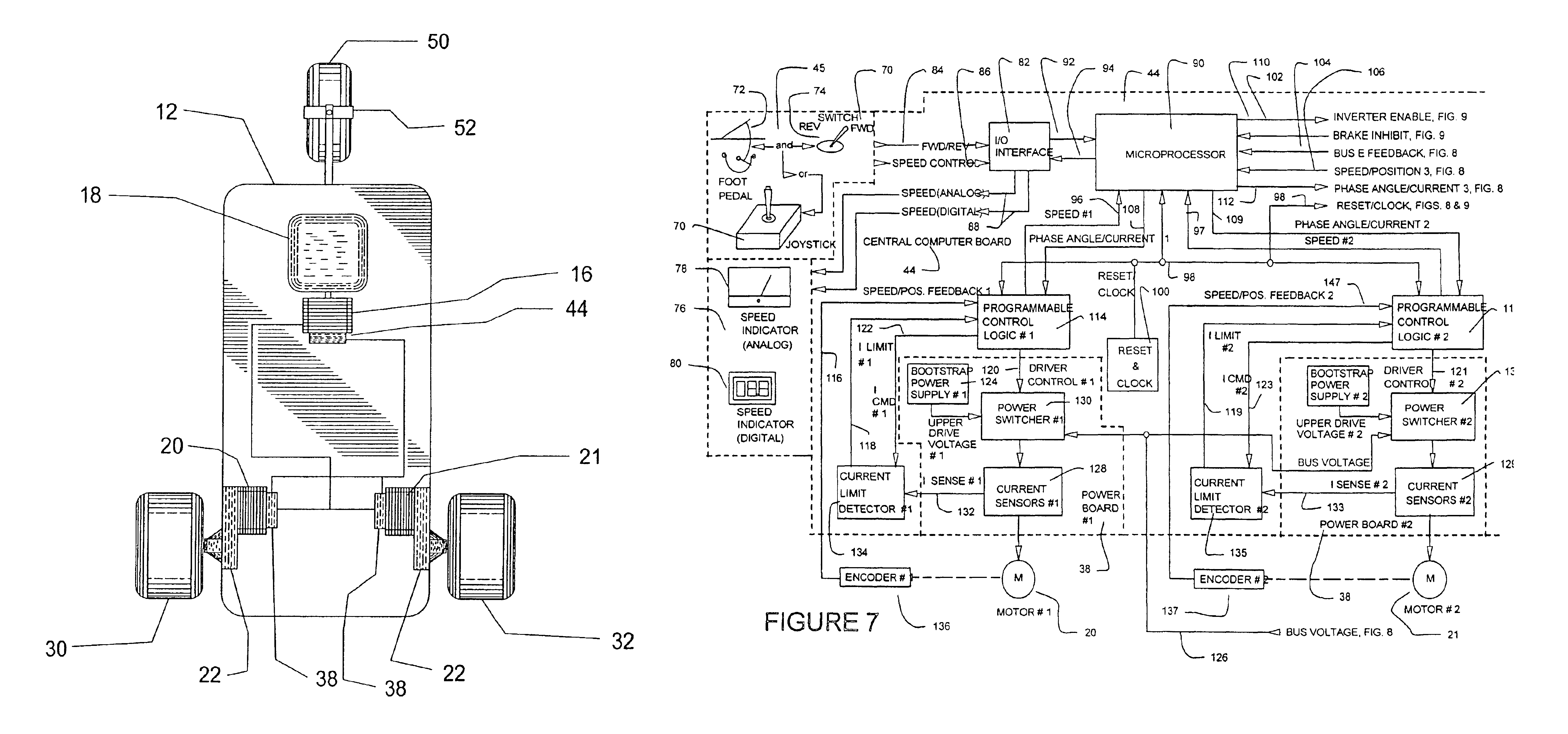
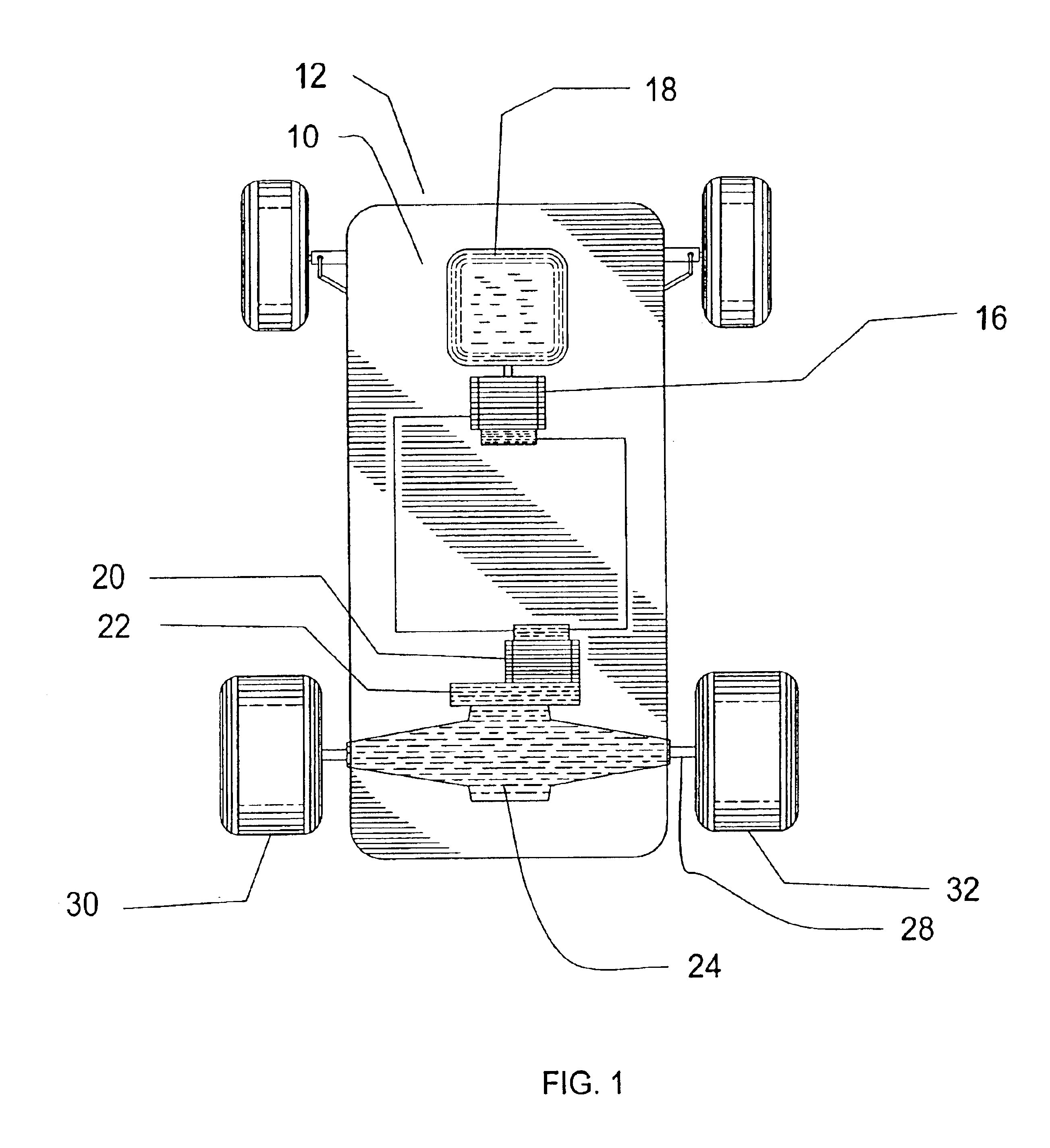
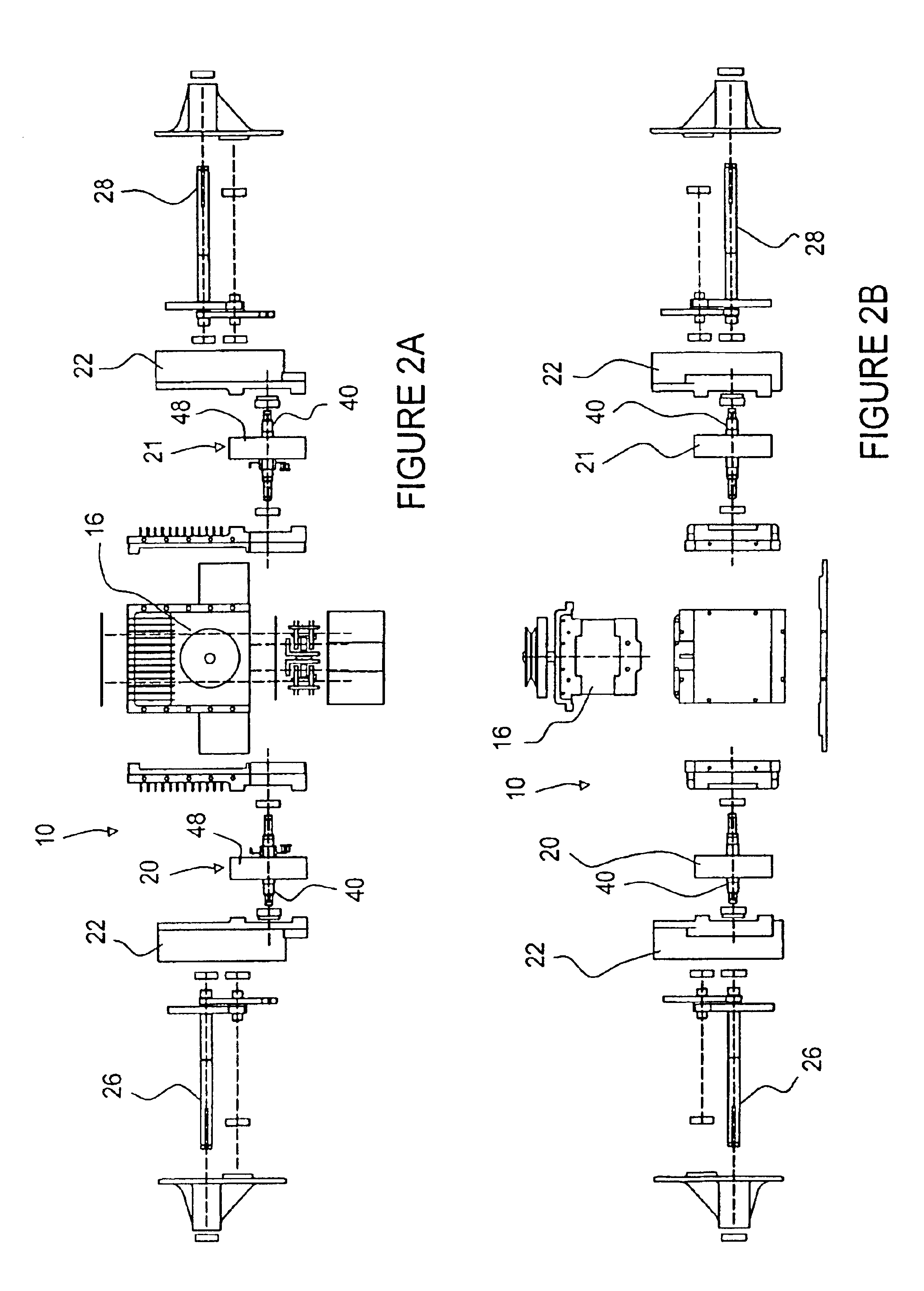
FIG. 1 shows a drive system 10 for a four-wheeled mower 12 with conventional steering 14. The drive system 10 includes an electric generator 16 which is driven by an internal combustion engine 18 and a motor 20 mounted to a gearbox 22 and standard mechanical differential 24 which drives the individual axles 26, 28 of the two rear wheels 30, 32. This configuration allows the engine 18 to operate continuously at its most efficient speed and eliminates the need for a transmission.

Advances in electric generators 16 and motors 22 have increased their efficiencies to the 80-90% range and improved their reliability. A comparison of different motors 22 and generators 16 was conducted to determine the best type for this drive system. The types considered were inverter-powered AC induction, brush-less dc and switched reluctance. Criteria for the selection were controllability, efficiency, reliability, input speeds, output torque at all speeds, size, construction, thermal management, noise, ma...


PUM


Abstract

A drive system which integrates an electric generator, one or more electric motors and an electronic control module is configured as a variable speed drive in either single, dual or four wheeled traction drive configurations for a mower. The generator is mechanically driven by the output shaft of an internal combustion engine to generate the electrical power for energizing the electric motors. A central computer in the electronic control module controls the output voltage of the generator and the speed and torque of each of the motors in the drive system. The speed input signal for the motors can be analog signals that come from sources such as a joystick, a potentiometer mounted on a steering wheel, control panel, foot pedal or remote location or digital signals from a digital device. Position / speed detectors on each motor and the generator send signals back to the central computer for closed-loop control of the generator and of the motors. The generator supplies the DC voltage to the power control board for each motor as commanded by the central computer. The rotor of each motor is connected to a gearbox for speed reduction and increased torque that is applied to the wheel mounted on the output shaft of the gearbox. When the motors are not being driven, the generator may optionally supply DC power to the input of an inverter that has an output to standard electric utility AC outlets that can be used to power auxiliary equipment.

Description

BACKGROUND OF THE INVENTIONThis invention relates to the manner of generating, controlling, and distributing electrical power from an electrical generator driven by an internal combustion engine. The generated electrical power is used to power computer-controlled electric motors used as the traction drive in multipurpose lightweight mowers, and to provide power to on-board mower attachments and external electrical equipment.Lightweight mowers exist today in numerous configurations and are purposefully built to meet the application needs related to the industry in which they are used. Typical examples of these mowers are: Ride on Lawn Mowers; Yard and Garden Tractors; Snow Blowers; Golf Carts and Utility Carts; Traffic / Parking Police Scooters; Postal Delivery Vehicles; Airport People Movers; Airport Tarmac Shuttle Vehicles; Disabled-Person Movers; Hybrid Electric Vehicles; Go-carts; and All-Terrain Vehicles. These vehicles require a power source that is typically directly or indirect...

Claims


Application Information

Patent Timeline
Patent Type & Authority Patents(United States)
IPC IPC(8): B60L11/18B60K6/04B60L15/20B60K6/00B60K7/00B60K1/02B60K1/00B60K17/04B60K6/46B60W10/06B60W10/08B60W20/00
CPCB60L11/1807B60L15/2045B60W10/06B60W10/08B60W20/00B60K6/46B60K1/02Y02T10/648B60K7/0007B60K17/043B60L2200/22B60L2210/20B60L2220/18B60Y2200/114B60Y2200/223B60Y2200/41B60Y2200/84B60Y2200/86Y02T10/6217Y02T10/6286Y02T10/646Y02T10/7005Y02T10/725Y02T10/7283Y02T10/62Y02T10/64Y02T10/72B60W10/30B60W10/04Y02T10/70
Inventor BRANDON, DENNISFLACK, ALLAN
Owner BRANDON DENNIS
Why Eureka
Try Eureka