

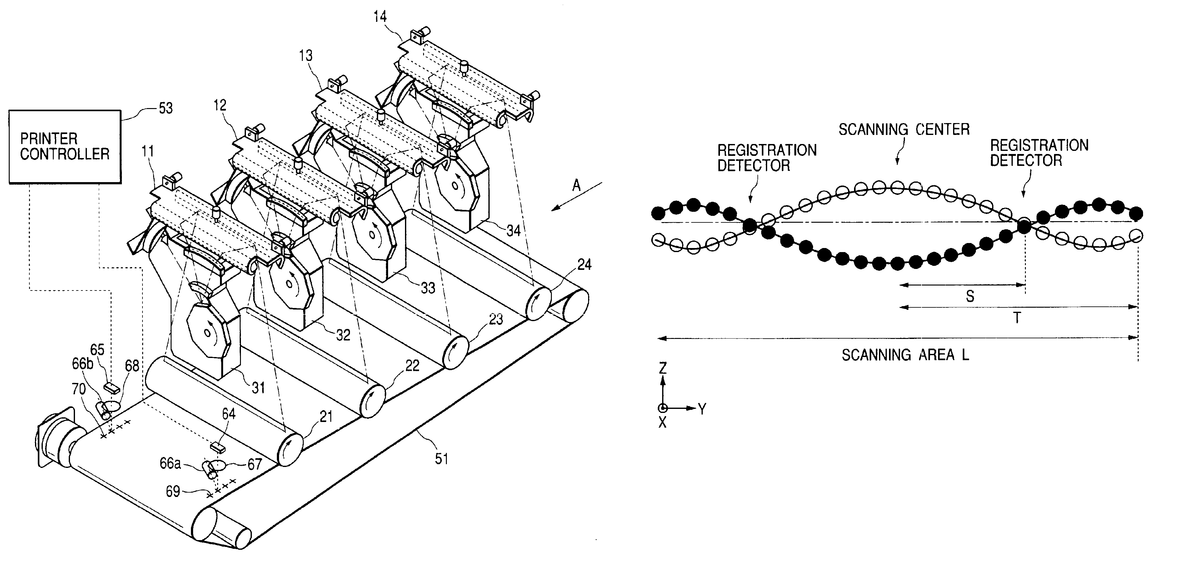
Color image forming apparatus with color registration detector
a color image and detector technology, applied in the direction of recording apparatus, instruments, electrographic processes, etc., can solve the problems of color misregistration, color misregistration, and deviation between the above-mentioned dot positions
- Summary
- Abstract
- Description
- Claims
- Application Information
AI Technical Summary
Benefits of technology
Problems solved by technology
Method used
Image

Examples
embodiment 1
(Embodiment 1)
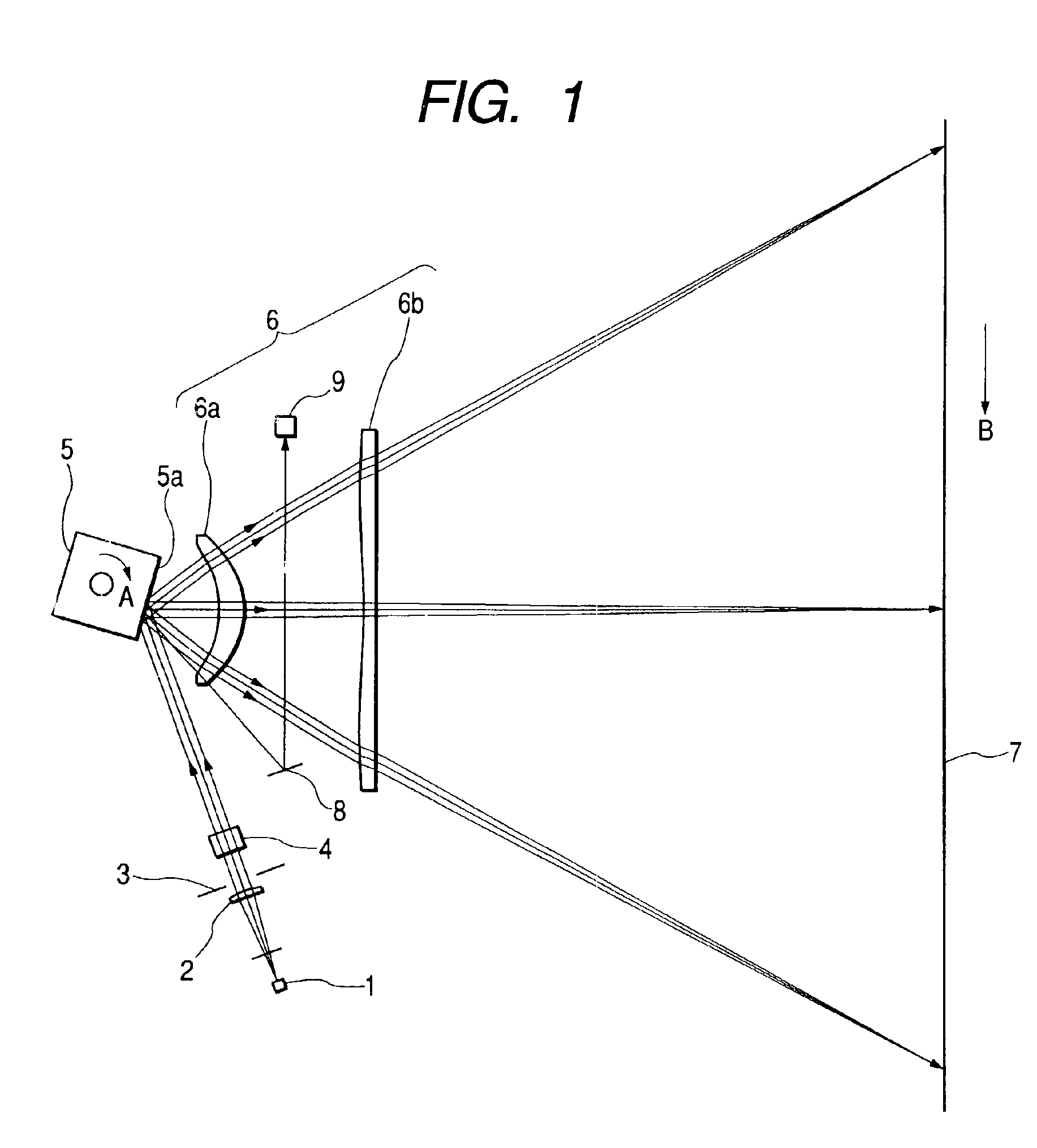
FIG. 1 is a cross-sectional view (main scanning cross-sectional view) in the main scanning direction of the essential portions of Embodiment 1 of the scanning optical apparatus of the present invention.
In FIG. 1, the reference numeral 1 designates light source means comprising, for example, a semiconductor laser or the lie. The reference numeral 2 denotes a condensing lens (collimator lens) which converts a divergent beam emitted from the light source means 1 into a substantially parallel beam or a convergent beam. The reference numeral 3 designates an aperture stop which limits the beam passing therethrough and shapes the beam shape. The reference numeral 4 denotes a cylindrical lens which has predetermined power only in a sub scanning direction, and causes the beam passed through the aperture stop 3 to be imaged as a substantially linear image on the deflecting surface (reflecting surface) 5a of a light deflector 5 which will be described later in the sub scanning cr...
embodiment 2
(Embodiment 2)
FIG. 11 is a cross-sectional view (main scanning cross-sectional view) of the essential portions of Embodiment 2 of the scanning optical apparatus of the present invention in the scanning direction.
The difference of the present embodiment from the aforedescribed Embodiment 1 is that the scanning line curvature adjusting mechanism is provided on the first lens 6a. In the other points, the construction and optical action of the present embodiment are substantially similar to those of Embodiment 1, whereby a similar effect is obtained.
That is, in the present embodiment, the scanning line curvature adjusting mechanism is provided on the first lens 6a of the first and second lenses 6a and 6b, and during the assembly of the scanning optical apparatus, detecting means 61 for detecting the position of the scanning line in the height direction thereof is disposed on the surface 7 to be scanned, and on the basis of the result of the detection obtained by the detecting means 61, ...
embodiment 3
(Embodiment 3)
FIG. 14 is a cross sectional view (main scanning cross-sectional view) of the essential portions of a scanning optical apparatus according to Embodiment 3 of the present invention in the scanning direction, and each of FIGS. 15A and 15B shows the curvature of the scanning line in FIG. 14. In FIGS. 14, 15A and 15B, the same elements as the elements shown in FIG. 1 are given the same reference characters.
The difference of the present embodiment from the aforedescribed Embodiment 1 is that detecting means is disposed at each of the positions of a plurality of image heights, and on the basis of the result of the detection obtained by each detecting means the curvature of the scanning line is adjusted so as to satisfy conditional expressions (1) and (2) which will be described later. In the other points, the construction and optical action of the present embodiment are substantially similar to those of Embodiment 1, whereby a similar effect is obtained.
That is, in the prese...
PUM
 Abstract
Description
Claims
Application Information