
Modular data storage device assembly

a data storage device and module technology, applied in the direction of instruments, furniture parts, electric apparatus casings/cabinets/drawers, etc., can solve the problems of increasing the heat inside the system, difficult to obtain, and additional problems in the cooling system design, so as to enhance the cooling effect of the storage devi

Inactive Publication Date: 2005-02-15
RABINOVITZ JOSEF
View PDF1 Cites 83 Cited by
  • Summary
  • Abstract
  • Description
  • Claims
  • Application Information

AI Technical Summary

Benefits of technology

In a third aspect of the present invention the modular data storage device assembly further includes a backplane. The backplane is disposed in the chassis and has a plurality of disk drive interface connectors that are mechanically coupled thereto. Each disk drive interface connector is connected to one of the disk data storage devices. The chassis design and the backplane design provide for blind mating and pluggability of the disk data storage devices into the backplane.
In a fifth aspect of the present invention the modular data storage device assembly includes a blower as a means of enhancing storage device cooling.

Problems solved by technology

In existing client / server network systems it is often difficult to obtain, in a timely manner, important diagnostic data and information corresponding to a component failure in order to facilitate the quick serviceability of the server.
Although the cooling of computer systems has always been a concern with computer designers to maintain high availability, the form factor of the chassis and the high demands for improved reliability of the client / server network systems with ever-increasing microprocessor power dissipation and system power consumption have created additional problems with cooling system design, especially in temperature monitoring and temperature control.
Not only are the high-end servers utilizing the newer high-powered processors, but are also utilizing multiple processors therein creating even more heat within the system.
One proposed solution was to just use higher speed, cooling fans, however, higher speed fans created increased noise levels of operation.
A disk drive with this capability is often referred to as “hot-plugable.” One of the problems with the use of removable disk drives arises when a user attempts to install a carrier including a hard drive or other peripheral device in a slot wherein the internal connector in a peripheral device bay is not compatible with the connector on the peripheral device.
If the peripheral device connector does not mate properly with the internal connectors in the bay, the user may jam the carrier more forcefully in the bay, which could result in damage to the connector assemblies or to the device carrier.
Another problem arises when a user attempts to utilize a peripheral device carrier that is not designed for the particular bay.
Further, if the device carrier is not the correct size or type, strain may be placed on the connectors, leading to damaged connections and loss of system reliability.

Method used


Image

  • Modular data storage device assembly
  • Modular data storage device assembly
  • Modular data storage device assembly

Examples


Embodiment Construction

U.S. Pat. No. 5,822,184 a modular data device assembly for a computer. In the description, specific materials and configurations are set forth in order to provide a more complete understanding of the present invention. But it is understood by those skilled in the art that the modular data device assembly can be practiced without those specific details. In some instances, well-known elements are not described precisely so as not to obscure the modular data device assembly.

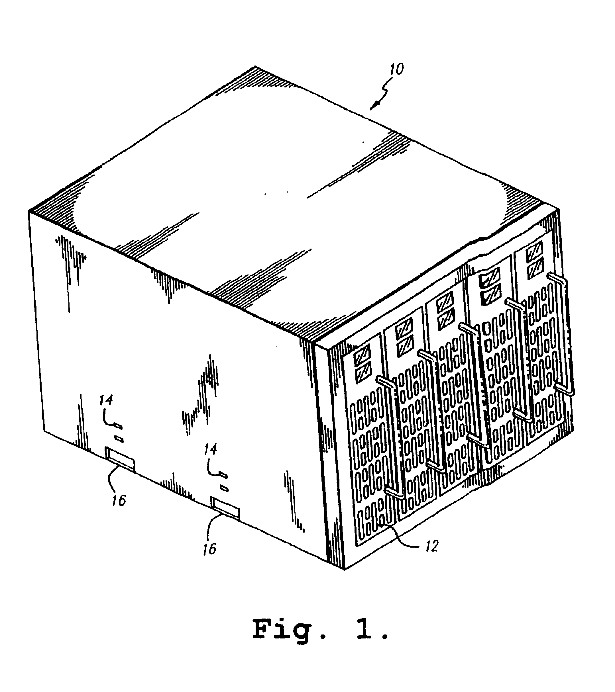
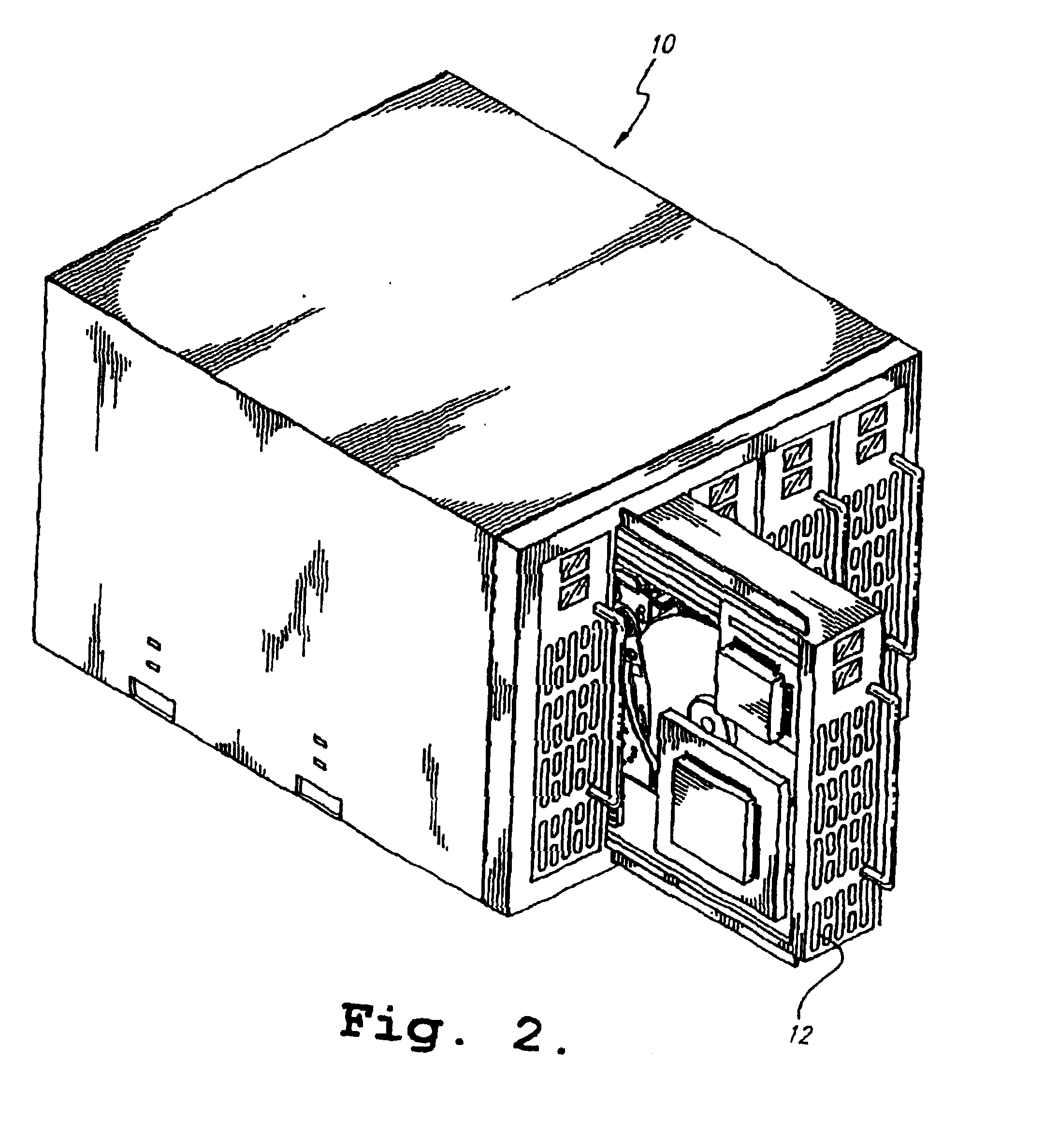
Referring to FIG. 1 in conjunction with FIG. 2 the modular data device assembly includes a housing 10 holding a plurality of modular data devices disposed in the housing 10. A motherboard is disposed in the back of the housing 10 and a bus interconnects the data devices 12 that operate under the direction of a controller. Although the following describes the modular data device assembly relative to a laptop, desktop or like personal computer, it is clear that it is easily adaptable to a computer of any size or capac...


PUM


Abstract

A modular data device assembly includes a chassis that has an open front and a back. The chassis also has exterior dimensions that correspond to the dimensions of an industry standard drive bay. The chassis further has a plurality of slots that are disposed inside the chassis. The modular data device also includes a plurality of disk data storage devices, a backplane, and a connector. Each disk data storage device is disposed in one of the plurality of slots. The backplane is disposed in the back of the chassis. The backplane has a plurality of connectors which are mechanically coupled thereto and each of which is connected to one of the disk data storage devices. The power source connector is mechanically and electrically coupled to the backplane.

Description

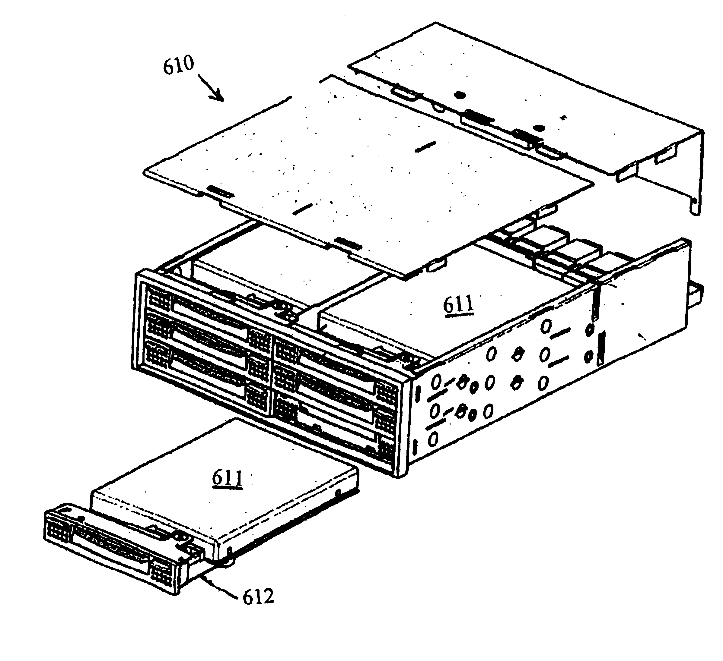
BACKGROUND OF THE INVENTION1. Field of the InventionThe present invention relates to an arrangement for mounting, connecting, cooling shielding and providing removability for disk data storage devices in a computer and more particularly to a modular data device assembly adapted to mount in an industry standard size slot.2. Description of the Prior Art and Related InformationU.S. Pat. No. 5,822,184 teaches a modular data device assembly for a computer is disclosed that has a housing that is designed to fit into a conventional, industry standard size expansion bay. Individual plug-in data storage devices such as hard disk drives or CD-ROM drives are disposed vertically in a stacked formation within the housing. A motherboard with plug-in connectors to which the drives are connected allows easy replacement of defective data devices, which devices slide in or out. The disk drives and modular data device assemblies may be arrayed in series or in parallel to a controller. By its modular s...

Claims


Application Information

Patent Timeline
IPC IPC(8): G06F1/18G11B33/12
CPCG06F1/184G11B33/128G11B33/126G06F1/187
Inventor RABINOVITZ, JOSEF
Owner RABINOVITZ JOSEF
Learn More