Optical fibres with special bending and dispersion properties

a technology of optical fibres and micro-bending, applied in the field of optical fibres, can solve the problems of multi-mode fibres and filling fractions of 18% or smaller, and achieve the effect of improving the macro-bending properties and the refractive index

Inactive Publication Date: 2005-02-15
CRYSTAL FIBRE AS
View PDF7 Cites 57 Cited by
  • Summary
  • Abstract
  • Description
  • Claims
  • Application Information

AI Technical Summary

Benefits of technology

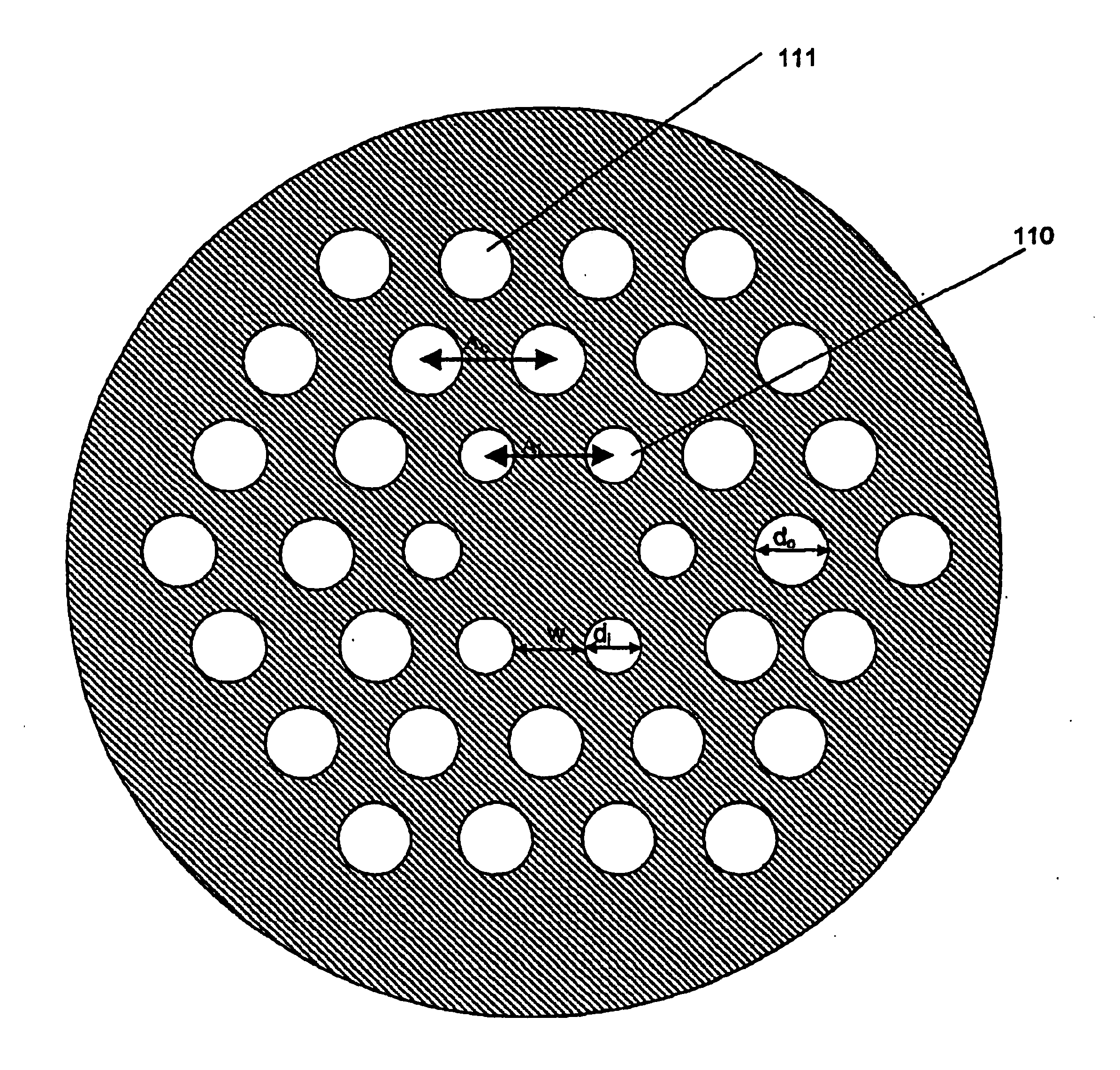
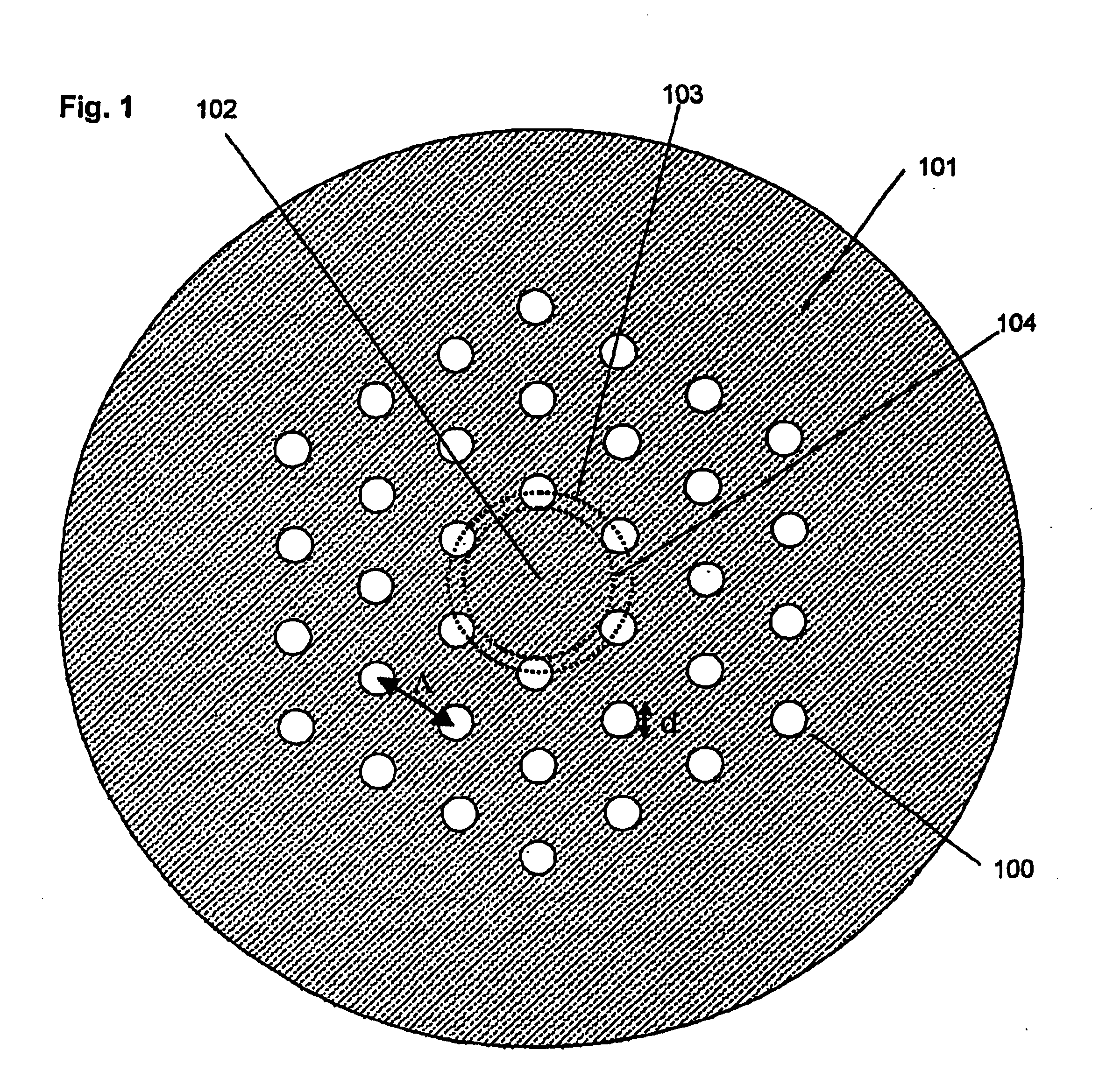
[0032]When having elongated innermost cladding features, it may be more appropriate to describe the core using an inner dimension—defined as the smallest dimension through the core centre that does not touch the innermost cladding features. In preferred embodiments, the inner cladding dimension is at least 2.0 μm, and preferably up to at least 25.0 μm. In other preferred embodiments, the inner core dimension may be smaller than the inner cladding feature centre-to-centre spacing Λi. This may improve the cut-off properties of the fibres.
[0048]For certain applications, it is an advantage that the core material (the background material of the core region) has a different refractive index than the cladding material. This allows flexibility of tailoring the dispersive properties of the fibres. This refractive index difference may be obtained e.g., by using different dopants in the two materials (e.g. silica doped to various degrees), different glasses, or it may be obtained simply by using different basis materials (e.g., different types of polymers).

Problems solved by technology

The main problem for the fibre designs disclosed in the prior art is, however, that above a certain air hole size, the fibres may become multi-mode.
It is a disadvantage of single-mode, micro-structured fibres with core diameters above 4 μm, which are known in the prior art, that they have filling fractions of 18% or smaller.

Method used


Image

  • Optical fibres with special bending and dispersion properties
  • Optical fibres with special bending and dispersion properties
  • Optical fibres with special bending and dispersion properties

Examples


Embodiment Construction

ent invention where a non-circular outer cladding is used. The orientation of the outer cladding is determined from the micro-structure in or around the core region. The outer cladding shape determines mechanically which bending direction(s) will be dominant for the fibre, and avoids bending directions that are most harmful for the fibre.

[0087]FIG. 18 shows schematically a fibre according to the present invention where an outer cladding with a non-circular and non-equilateral polygonal outer shape is used. During bending, this shape will mechanically favour bending of the fibre in certain direction compared to others and thereby provide new means for controlling macro-bending losses properties as well as stripping off of higher order modes, and, thereby, expand the single-mode operation range of the fibre.

[0088]FIG. 19 shows schematically another fibre according to the present invention where an elliptical outer shape is used and the overcladding is made from the same material as th...


PUM

PropertyMeasurementUnit
wavelengthsaaaaaaaaaa
operating wavelengthaaaaaaaaaa
bend radiusaaaaaaaaaa

Abstract

A microstructured optical fiber having a specially designed cladding to provide single mode waveguidance and low sensitivity to bending losses. In one aspect the optical fiber has an inner and an outer cladding each comprising elongated features. The inner cladding features have normalized dimensions in the range from 0.35 to 0.50 and the outer cladding features have normalized dimensions in the range from 0.5 to 0.9, where the normalization factor is a typical feature spacing. The fiber is further characterized by a feature spacing of the inner cladding larger than 2.0 micron. In a second aspect, the fiber has a special non-circular and non-equilateral-polygonial outer cross-sectional shape to mechanically ensure bending in predetermined directions that are favourable with respect to low bending losses. The present invention provides fibers, which are less sensitive to macro-bending losses than presently known single-mode fibers with similar sized mode areas, and provides robust, single-mode, large-mode area fibers for long-distance optical transmission and fibers with special dispersion properties.

Description

[0002]This is a nationalization of PCT / DK01 / 00746 filed Nov. 12, 2001 and published in English.FIELD OF THE INVENTION[0003]The present invention relates to electromagnetic waveguides, especially optical fibres, having micro-structures in core and / or cladding region(s).BACKGROUND OF THE INVENTION[0004]While transmission speeds are pushed into the Tbit range for modern, multi-channel telecommunication systems, a large interest is pointed towards new optical fibres with relatively large mode areas. One of the key issues is to avoid disturbance of individual channels, while these are transmitted over a fibre link. The disturbance is mainly related to non-linear effects in the fibres—effects that can be suppressed or in practice eliminated by the use of fibres with large mode areas and / or special dispersion properties.[0005]For many applications, a large mode area can, however, not be tolerated using presently known fibres, since such fibres exhibit high macro-bending losses. This is e.g...

Claims


Application Information

Patent Timeline
Patent Type & Authority Patents(United States)
IPC IPC(8): C03B37/012G02B6/10G02B6/02G02B6/024
CPCC03B37/01205G02B6/024G02B6/02338G02B6/02357G02B6/02361G02B6/02371C03B2203/02C03B2203/10C03B2203/14C03B2203/32G02B6/0239C03B2203/42
Inventor BROENG, JESLIBORI, STIG EIGIL BARKOUBJARKLEV, ANDERS OVERGAARD
Owner CRYSTAL FIBRE AS
Why Eureka
Try Eureka