
Power semiconductor device with cut-off ring structure and manufacturing method of power semiconductor device

A technology of power semiconductor and cut-off ring, which is applied in semiconductor/solid-state device manufacturing, semiconductor devices, transistors, etc., and can solve problems such as drain potential on non-conductive polysilicon bands and device leakage.

Pending Publication Date: 2019-12-06
WUXI NCE POWER
View PDF0 Cites 0 Cited by
  • Summary
  • Abstract
  • Description
  • Claims
  • Application Information

AI Technical Summary

Problems solved by technology

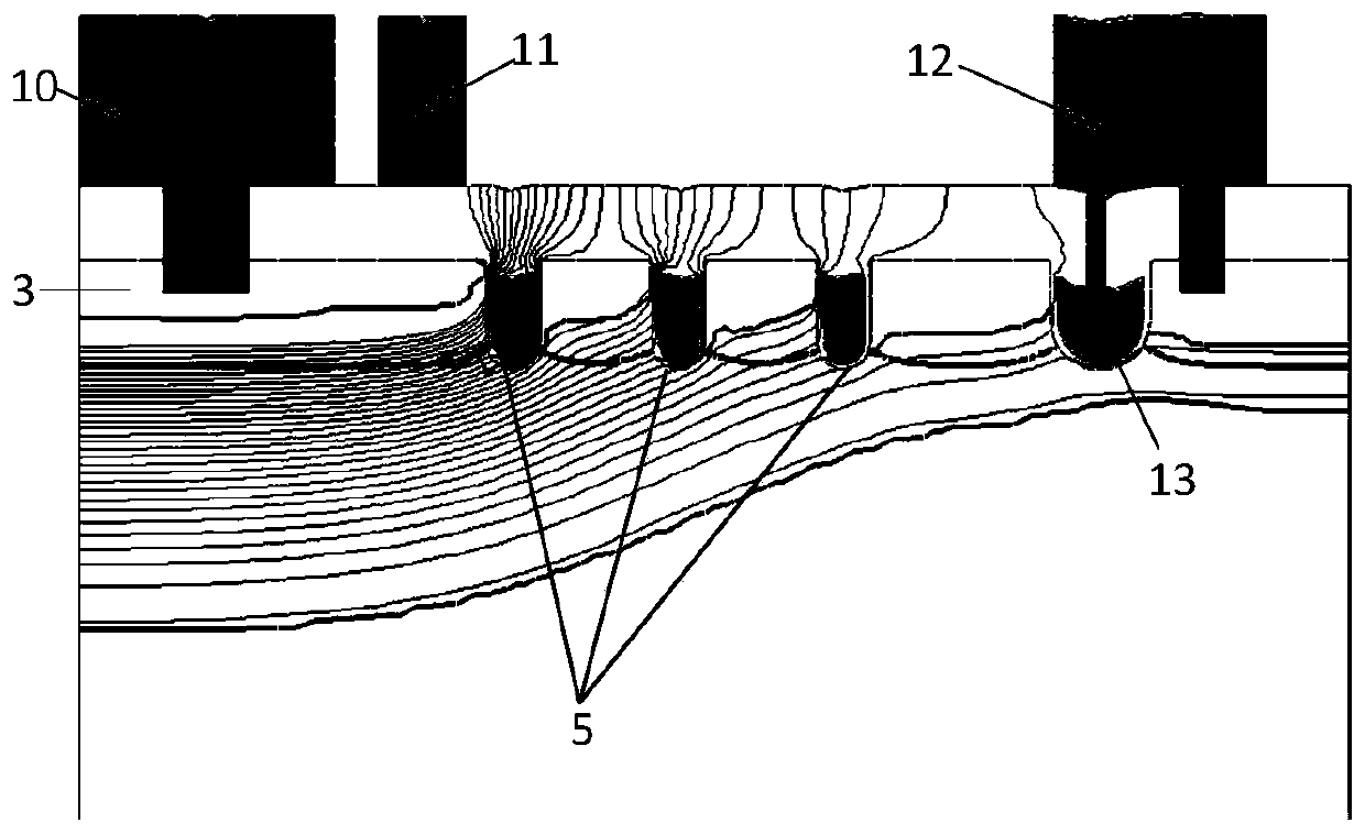
In the actual production process, when the trench depth becomes shallow, serious leakage occurs when the device withstands voltage. After simulation verification, as shown in figure 2 Shown is the potential distribution diagram of the traditional trench MOSFET structure when it withstands voltage. When the device withstands voltage, the stop ring does not completely cut off the electric field, which leads to the leakage of the device. After research, it is found that the first in the traditional trench MOSFET Since the stop ring metal 12 in the through hole on the side away from the cell region of the third type trench 13 is in contact with the P-type body region, it is impossible to bring the conductive polysilicon in the third type trench 13 to a drain potential. The potential of the conductive polysilicon in the three types of trenches 13 is always lower than the potential of the drain

Method used


Image

  • Power semiconductor device with cut-off ring structure and manufacturing method of power semiconductor device
  • Power semiconductor device with cut-off ring structure and manufacturing method of power semiconductor device
  • Power semiconductor device with cut-off ring structure and manufacturing method of power semiconductor device

Examples


Embodiment Construction

[0041]It should be noted that, in the case of no conflict, the embodiments of the present invention and the features in the embodiments can be combined with each other. The present invention will be described in detail below with reference to the accompanying drawings and examples.

[0042] In order to enable those skilled in the art to better understand the solutions of the present invention, the following will clearly and completely describe the technical solutions in the embodiments of the present invention in conjunction with the accompanying drawings in the embodiments of the present invention. Obviously, the described embodiments are only Embodiments of some, but not all, embodiments of the present invention. Based on the embodiments of the present invention, all other embodiments obtained by persons of ordinary skill in the art without making creative efforts shall fall within the protection scope of the present invention.

[0043] It should be noted that the terms "fi...


PUM


Abstract

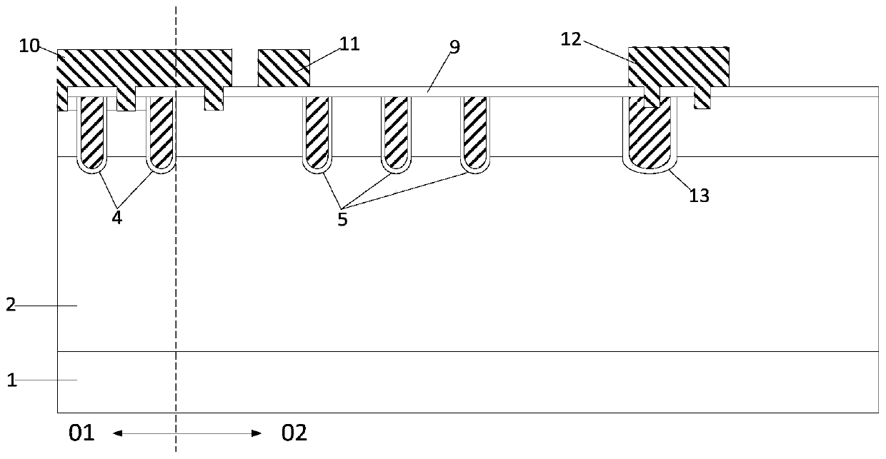
The invention relates to the technical field of semiconductors, and particularly discloses a power semiconductor device with a cut-off ring structure. The power semiconductor device comprises a semiconductor substrate, wherein a cellular region is located in the central region of the semiconductor substrate, and a terminal protection region is located on the outer ring of the cellular region and arranged around the cellular region; the cut-off ring structure which is arranged around the periphery of a groove of a second type in a body region of a second conductive type of the terminal protection region, wherein the cut-off ring structure comprises a third type groove, a fourth type groove and cut-off ring metal; the groove bottoms of the third type groove and the fourth type groove extendinto the first conductive type epitaxial layer, and the cut-off ring metal is located above a third type groove and a fourth type groove, and the cut-off ring metal can extend into the epitaxial layerof the first conductive type through the fourth type groove. The invention further discloses a manufacturing method of the power semiconductor device with the cut-off ring structure. According to thepower semiconductor device with the cut-off ring structure, the cut-off capability of the power semiconductor device can be improved, and the electric leakage of the device is prevented.

Description

technical field [0001] The invention relates to the field of semiconductor technology, in particular to a power semiconductor device with a stop ring structure and a method for manufacturing the power semiconductor device with the stop ring structure. Background technique [0002] Such as figure 1 Shown is a schematic structural diagram of a conventional trench MOSFET structure. Such as figure 1 As shown, the trench MOSFET structure includes a cell area and a terminal protection area, the cell area is located in the central area of ​​the device, and a stop ring structure is arranged in the terminal protection area. figure 1 The shown stop ring is composed of a third type of trench 13. Taking an N-type device as an example, the surface of the third type of trench 13 located in the P-type body region is covered by an insulating dielectric layer, and the bottom of the trench enters the N-type epitaxial layer. , and surround the second type of groove 5 . A through hole is pr...

Claims


Application Information

Patent Timeline
IPC IPC(8): H01L29/786H01L29/40H01L21/336
CPCH01L29/407H01L29/404H01L29/78609H01L29/66742
Inventor 朱袁正周锦程
Owner WUXI NCE POWER
Learn More