Image forming apparatus and method of developing an electrostatic latent image

a technology latent image, which is applied in the field of image forming apparatus, can solve the problems of ineffective cleaning of the developing sleeve with jet air, toner particles, fouling of the developing sleeve surface, etc., and achieves the fouling of the developing sleeve, the accelerated trapping of toner particles, and the poor fluidity of fine toner particles

Inactive Publication Date: 2005-02-15
RICOH KK
View PDF26 Cites 25 Cited by
  • Summary
  • Abstract
  • Description
  • Claims
  • Application Information

AI Technical Summary

Benefits of technology

It has been found that toner filming on a developer-bearing member (developing member) such as a developing sleeve is attributed partly to poor fluidity of fine toner particles. Once fine toner particles deposit on the developing sleeve, they are not readily adhered to carrier particles. Further, grooves and other roughness of the developing sleeve surface will accelerate the trapping of the toner particles. It has also been found that when a two-component developer used has a toner having a large proportion of fine particles and when a developer regulating member (a doctor blade) used to regulate the amount or thickness of the developer carried by the developer sleeve is grounded to form an electric field between the doctor blade and the developing sleeve, fouling of the developing sleeve with the toner can be prevented while uniformity of the optical density of a 100% solid image can be improved.

Problems solved by technology

One problem with the conventional image forming devices using fine toner particles is fouling of a surface of a developer bearing member such as a developing sleeve.
Once filming occurs, cleaning of the developing sleeve with jet air is no longer effective and a solvent must be used to clean it.

Method used


Image

  • Image forming apparatus and method of developing an electrostatic latent image
  • Image forming apparatus and method of developing an electrostatic latent image

Examples


example 1

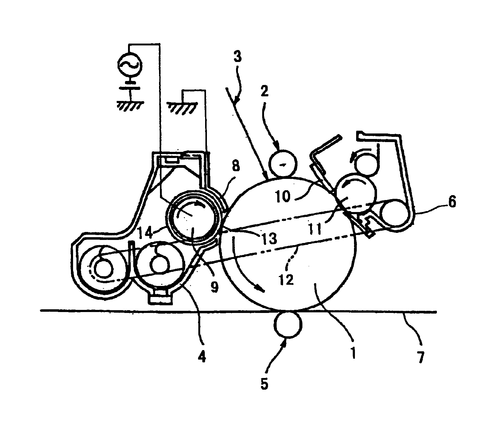
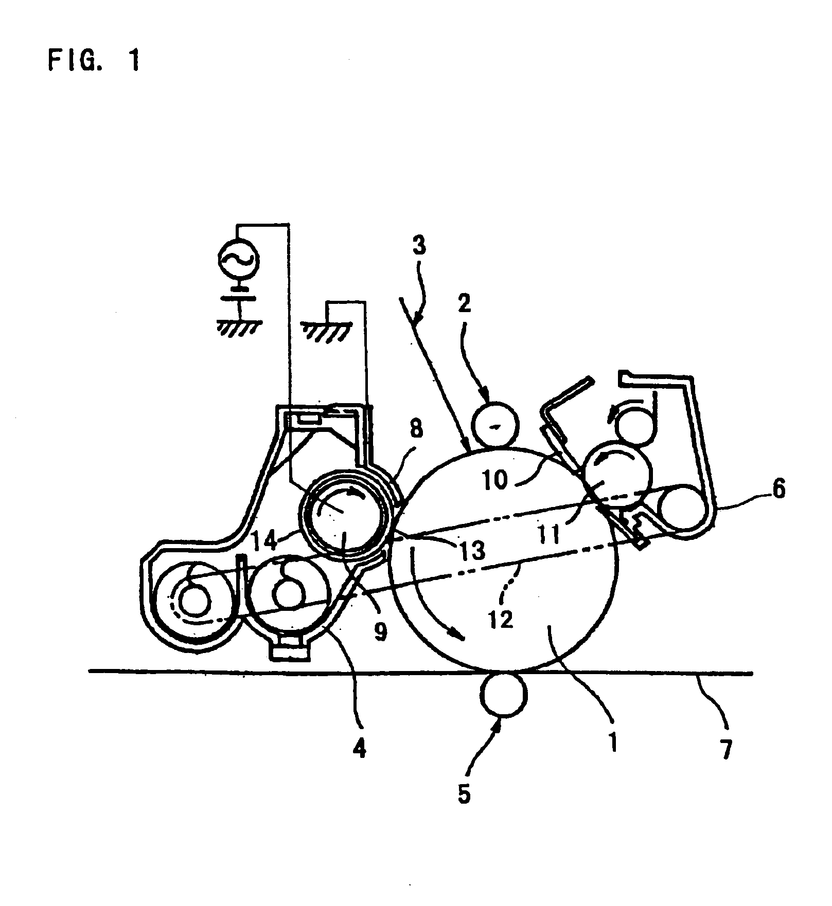
4 Parts of Toner (A) obtained above and 96 parts of Carrier (I) obtained above were thoroughly mixed with a Turbler mixer to obtain a developer. This was charged in a developing unit of the above copying machine (IMAGIO MF4570) in which the doctor blade was grounded, the gap between the doctor blade and the developing cylinder was adjusted to 0.34 mm and the toner-recycling path was connected to the waste toner collecting tank. The copying machine was operated to obtain 50,000 copies. Thereafter, three copies of 100% solid image (A3 size) and three copies of 100% white image (A3 size) were produced to evaluate the uniformity in the density of the solid images and the background stains of the white images. The results are summarized in Table 3. Good results are obtained. Uniformity in density is represented by a difference between the maximum and minimum optical densities. A value of less than 0.20 is desired. In evaluation of the background stains, rank 5 is the best and indicates t...

example 2

Example 1 was further continued. Thus, after the copying machine had been set so that the recovered toner was recycled to the developing unit, 50,000 copies were produced. Then, three copies of 100% solid image (A3 size) and three copies of 100% white image (A3 size) were produced to evaluate the uniformity in the density of the solid images and the background stains of the white images. The results are summarized in Table 3. Good results are obtained. After the production of copies, the developing sleeve was observed with naked eyes. The sleeve was found to be clean as in the initial state.

example 3

The copying machined after Example 2 was cleaned into the state similar to that before the start of the test in Example 1. To the cleaned machine, a developer obtained by mixing 4 parts of Toner (B) obtained above and 96 parts of Carrier (I) obtained above using a Turbler mixer was charged. The doctor blade was grounded, the gap between the doctor blade and the developing cylinder was adjusted to 0.34 mm and the toner recycling path was connected to the developing unit in the same manner as that in Example 2. The copying machine was operated to obtain 50,000 copies. Thereafter, three copies of 100% solid image (A3 size) and three copies of 100% white image (A3 size) were produced to evaluate the uniformity in the density of the solid images and the background stains of the white images. The results are summarized in Table 3. Better results were obtained with respect to the background stains as compared with the case of Example 2, though the uniformity of the density of the solid ima...


PUM


Abstract

An image forming apparatus including a photoconductor, and a developing unit having a developing sleeve for carrying a developer and a developer regulating plate for regulating the amount of the developer carried on the sleeve, wherein the developer is composed of a carrier and a toner, wherein that portion of the toner which has a particle diameter of 2.0-4.0 μm accounts for 30-70% of a total number thereof, and wherein the developer regulating plate is grounded so that when the developing sleeve is applied with a bias voltage, an electric field is formed between the developer regulating plate and the developing sleeve, whereby toner deposits on the developing sleeve are transferred to the developer regulating plate.

Description

BACKGROUND OF THE INVENTION1. Field of the InventionThe present invention relates to an image forming apparatus for use in a copying machine, a facsimile, a laser beam printer, or the like, adapted to form an image by visualizing an electrostatic latent image with a two-component developer containing a mixture of toner and carrier.2. Discussion of Prior ArtIn a known image forming apparatus using electrophotography, an electrostatic latent image is formed on a surface of a photoconductor having a photoconductive layer serving as an image bearing member by exposing the surface of the photoreceptor which has been uniformly charged. Subsequently, the electrostatic latent image on the photoreconductor is developed with toner to form a toner image. The toner image is then transferred to a recording member such as a transfer sheet. The transferred toner image is finally fixed on the recording member by application of heat and pressure.As the developer, a single component developer compose...

Claims


Application Information

Patent Timeline
Patent Type & Authority Patents(United States)
IPC IPC(8): G03G13/06G03G13/09G03G9/08G03G9/087G03G9/113G03G15/08
CPCG03G13/09G03G9/0819
Inventor MATSUDA, HIROAKIIWAMOTO, YASUAKINAKAI, HIROSHIHIGUCHI, HIROTOSHU, BINGKONDO, MAIKOSASAKI, FUMIHIRO
Owner RICOH KK
Why Eureka
Try Eureka