
Optical system for reinforcing optical tweezers capturing force
a technology of optical system and force, which is applied in the direction of nuclear engineering, manufacturing tools, instruments, etc., can solve the problems of increased spherical aberration, difficult control and use of optical tweezers to trap micro particles, and failure to catch micro particles
- Summary
- Abstract
- Description
- Claims
- Application Information
AI Technical Summary
Benefits of technology
Problems solved by technology
Method used
Image

Examples
Embodiment Construction
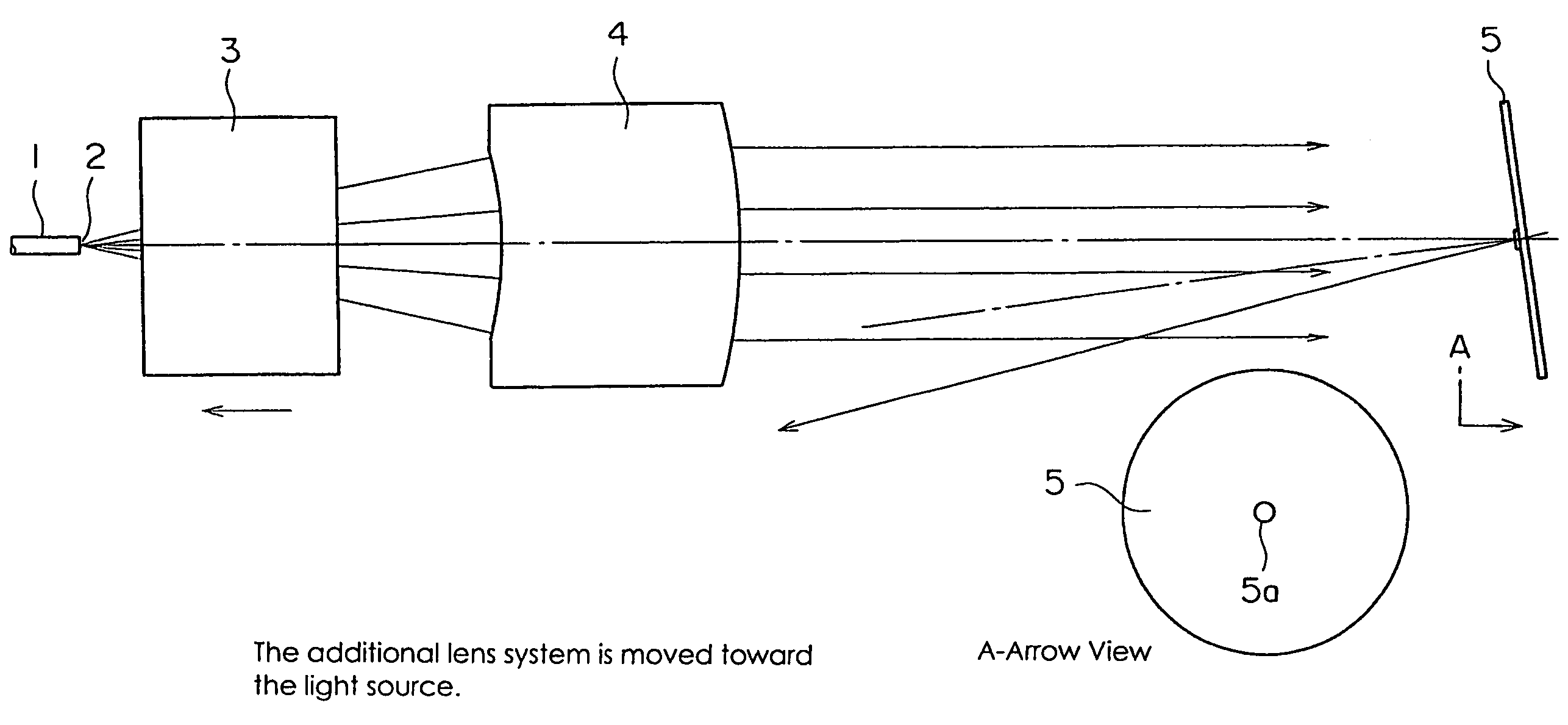
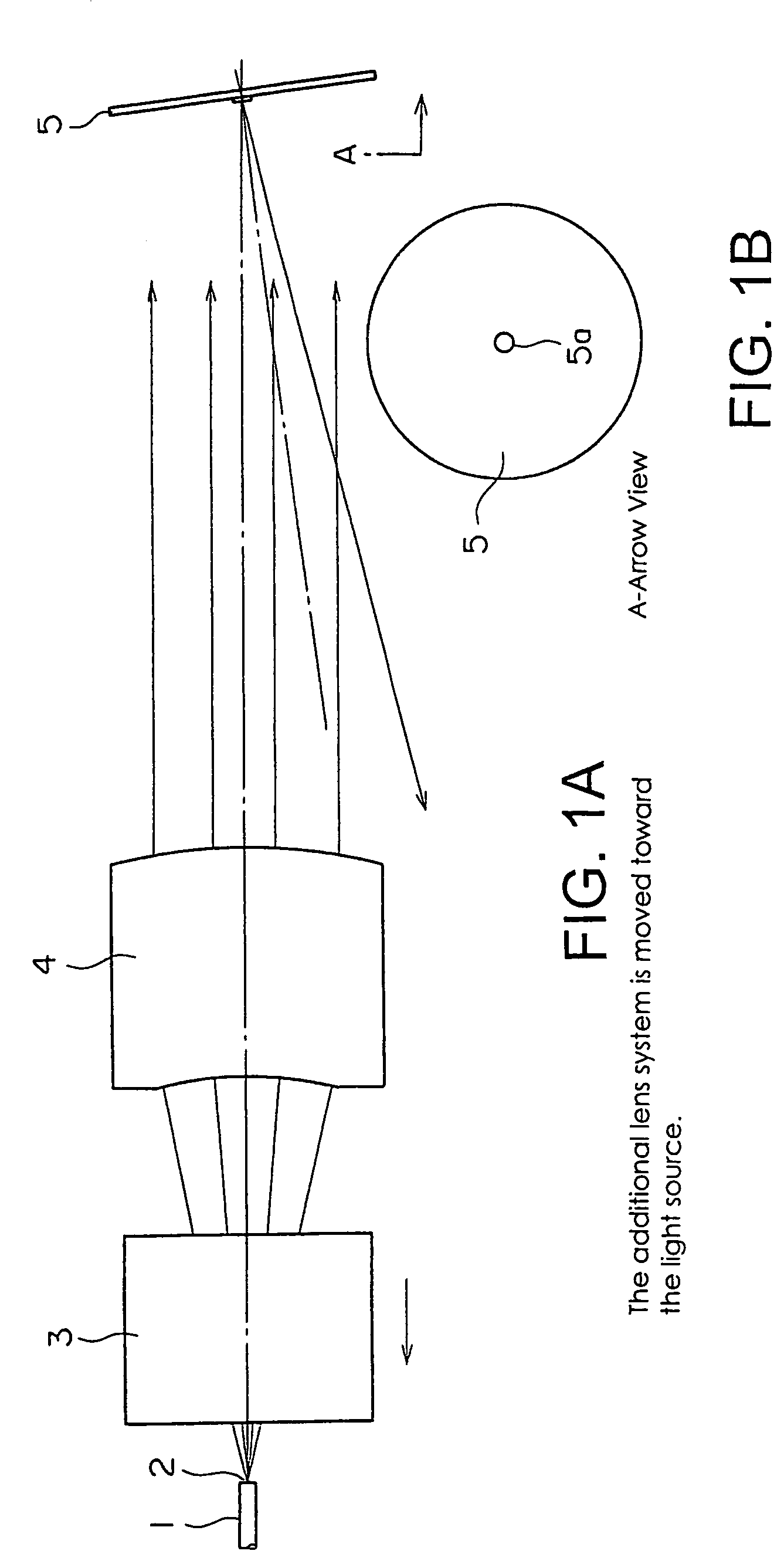
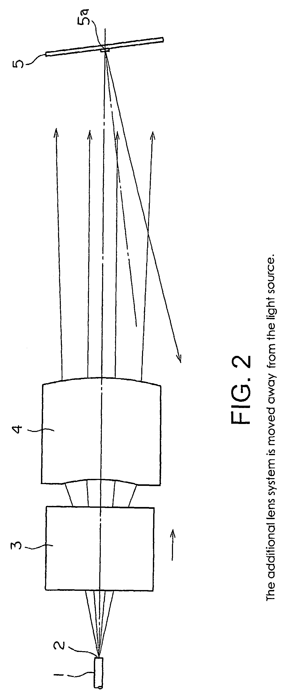
[0033]The principle of the optics of the present invention is described in the following referring to the drawings. FIGS. 1A and 1B shows the optics of the present invention where the additional lens system is moved toward the light source. FIG. 2 shows the optics of the present invention where the additional lens system is moved away from the light source.
[0034]In FIGS. 1A, 1B and 2, 1 denotes the laser fiber light source, 2 the emission port, 3 the additional lens system, 4 the collector lens and 5 the spot mirror. These components are arranged as shown in the figures. The additional lens system (3) moves along the optical axis, between the emission port (2) and the collector lens (4), as driven by a suitable known means of travel (not shown). The additional lens system is mounted on and removed from the optical axis using a suitable means of attachment.
[0035]The compound focal distance of the additional lens system (3) is infinity (no power lens). The additional lens system consi...
PUM
 Abstract
Description
Claims
Application Information