Spiral magnetic transmitter for position measurement system

a magnetic transmitter and position measurement technology, applied in the direction of measurement devices, converting sensor output, medical science, etc., can solve the problems of difficult position and orientation measurement, undesirable field distortion, and the inability to perform complex surgery and diagnostic procedures, so as to achieve enhanced operation

Inactive Publication Date: 2005-02-15
NORTHERN DIGITAL
View PDF12 Cites 122 Cited by
  • Summary
  • Abstract
  • Description
  • Claims
  • Application Information

AI Technical Summary

Benefits of technology

The present invention relates to a spiral magnetic transmitter for position measurement system. In the present invention, the disclosed transmitters have enhanced operation when the sensor approaches the transmitter

Problems solved by technology

In the medical environment, such systems are used to precisely locate an instrument or other object within the human body, thereby permitting complex methods of surgery and diagnostics to be carried out where accuracy in location is essential.
However, when the sensor approaches the plane of the transmitter loops, position and orientation measurement become difficult as the vectors from the transmitter loops become highly parallel.
Dipole systems also suffer from the phenomenon of magnetic cross-coupling, as the magnetic field from one dipole element induces current in another adjacent element which induced current is then re-radiated by that element, thereby producing undesirable field distortions.
Methods of preventing or eliminating such re-radiations are known in the art but require increased complexity in transmitter driver circuitry.
Prior art non-dipole systems also suffer from this re-radiation effect.
This phenomenon causes numerous difficulties when attempting to determine position and/or orientation of an object within a prescribed space.
In the Blood system, when the sensor approaches the

Method used


Image

  • Spiral magnetic transmitter for position measurement system
  • Spiral magnetic transmitter for position measurement system
  • Spiral magnetic transmitter for position measurement system

Examples


first embodiment

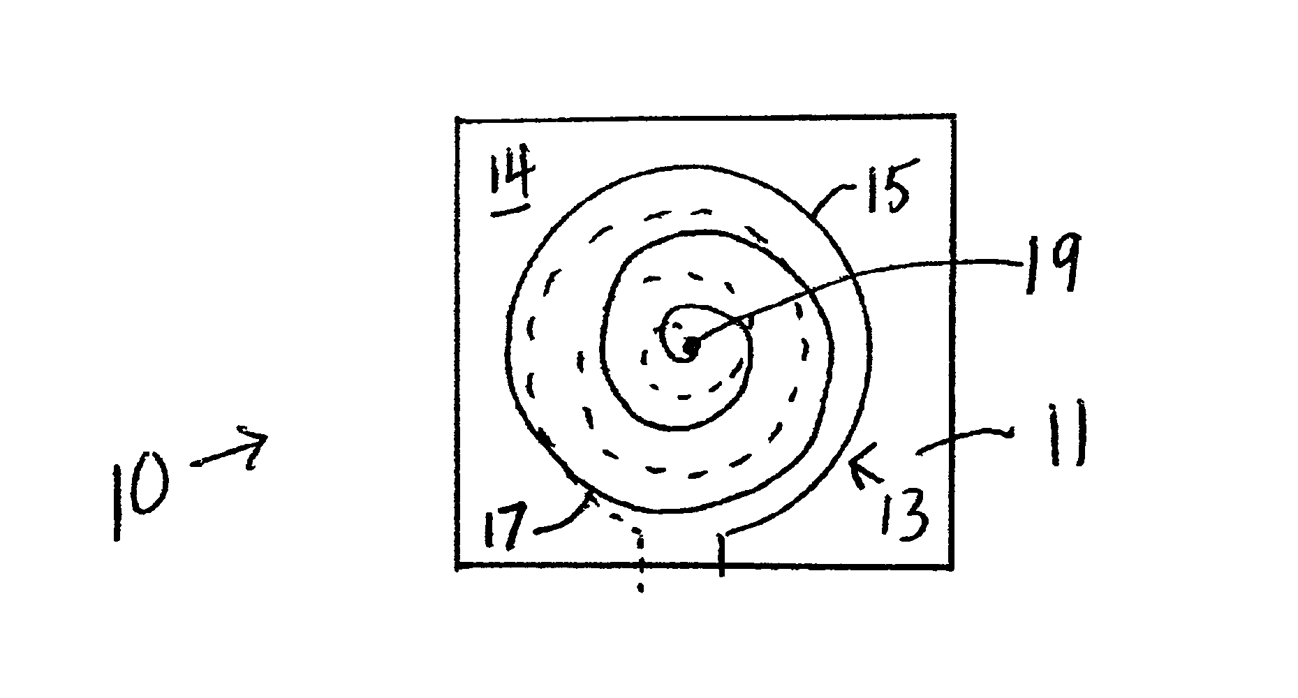
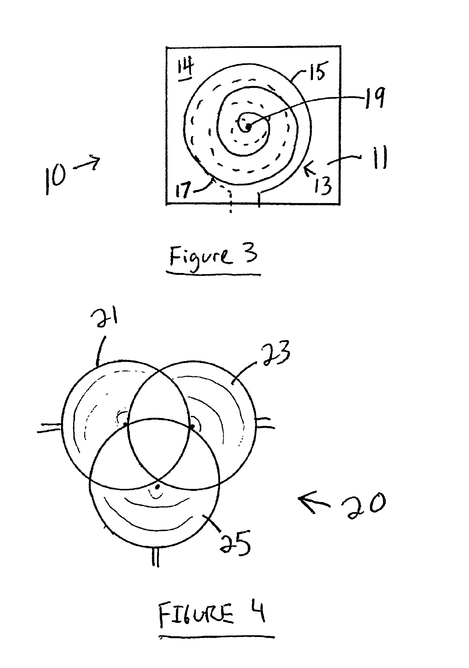
With reference now to FIG. 3, antenna in accordance with the teachings of the present invention is generally designated by the reference numeral 10 and is seen to include a substrate 11 that may comprise a PC board, and a transmitter generally designated by the reference numeral 13 including a spiral shape 15 mounted on the top surface 14 of the PC board, and a corresponding spiral shape 17 shown in phantom mounted on the bottom surface of the PC board. The shapes 15 and 17 are connected by a feed through 19 at the center thereof.

second embodiment

With reference to FIGS. 4-6, transmitter is generally designated by the reference numeral 20 and is seen to include three spiral transmitter coils 21, 23 and 25 associated with one another in overlapping configuration as shown in FIG. 4.

As seen in FIG. 5, the transmitter 20 may be mounted on a substrate 27 such as, for example, a PC board. If desired, in keeping with the teachings of FIG. 3, each of the spiral coils 21, 23 and 25 may also be coupled to an additional coil mounted beneath the substrate 27 and electrically connected to each respective one of the coils 21, 23 or 25 by respective feed throughs (not shown).

FIG. 6 shows a top view of the configuration shown in FIG. 5.

In one preferred configuration, the transmitters 10, 21, 23 and 25 may be constructed of a radius of 5 inches each consisting of two layers of conductor with 67 turns per layer and a pitch of 0.075 inches. Such a transmitter has an inductive of about 1.53 mH and a DC resistance of approximately 5.2 Ohms.

FIGS. ...


PUM


Abstract

A transmitter consists of a plurality of magnetic transmitters, each of which is substantially planar and made of a spiral shaped conductor. The result is a transmitter having a substantially uniform cross-sectional current density along the radial direction of the spiral from the center to the periphery. Near the plane of a given spiral, magnetic vectors produced by such a conductor arrangement have improved angular characteristics as compared to prior art systems. This results in a larger region with useful vector crossing angles and operation of the system is enhanced as compared to prior art techniques. The transmitters produce magnetic fields which have a monotonically increasing intensity as one approaches the center of the transmitter spiral from any given direction. This feature simplifies and increases the accuracy of sensor position determination. If desired, the turns of the spiral transmitter may become closer together as one goes from the periphery to the center thereof to thereby concentrate the magnetic field more centrally of the transmitter. Transmitters having one or two spiral coils are also contemplated.

Description

BACKGROUND OF THE INVENTIONThe present invention relates to a spiral magnetic transmitter for position measurement system. The present invention is generally in the field relating to devices for measuring the position of receiving antennas with respect to transmitting antennas using magnetic fields. Some such systems are able to measure position and orientation in six degrees of freedom, including translative motion in the three coordinate directions x, y and z, and orientation in the three orientation coordinates pitch, roll and azimuth. The present invention is equally applicable to systems designed to measure in fewer or greater than six degrees of freedom.In the prior art, it is known to use magnetically based position and orientation measuring systems in the fields of biomechanics and medical diagnostics. In those fields, a sensor assembly is mounted on a point of interest and the position of that point is determined relative to a fixed transmitter to precisely show the relativ...

Claims


Application Information

Patent Timeline
IPC IPC(8): G01D5/12G01D5/20A61B5/06
CPCG01D5/2086A61B5/06A61B5/062
Inventor ASHE, WESTLEY
Owner NORTHERN DIGITAL
Why Eureka
Try Eureka