Unlock instant, AI-driven research and patent intelligence for your innovation.

Simulation device

Active Publication Date: 2005-02-15
MITSUBISHI ELECTRIC CORP
View PDF6 Cites 18 Cited by
  • Summary
  • Abstract
  • Description
  • Claims
  • Application Information

AI Technical Summary

Benefits of technology

The present invention has been made to solve the above-mentioned problems. An object of the present invention is to provide a simulation device able to make an interference check without omission in an interference detection in a shorter time than actual machining.

Problems solved by technology

Recently, with an increasing complexity of structure of a machine tool, its operations are more complicated.
However, omission can occur in an interference detection because of low accuracy of an interference check.

Method used


Image

  • Simulation device
  • Simulation device
  • Simulation device

Examples


first embodiment

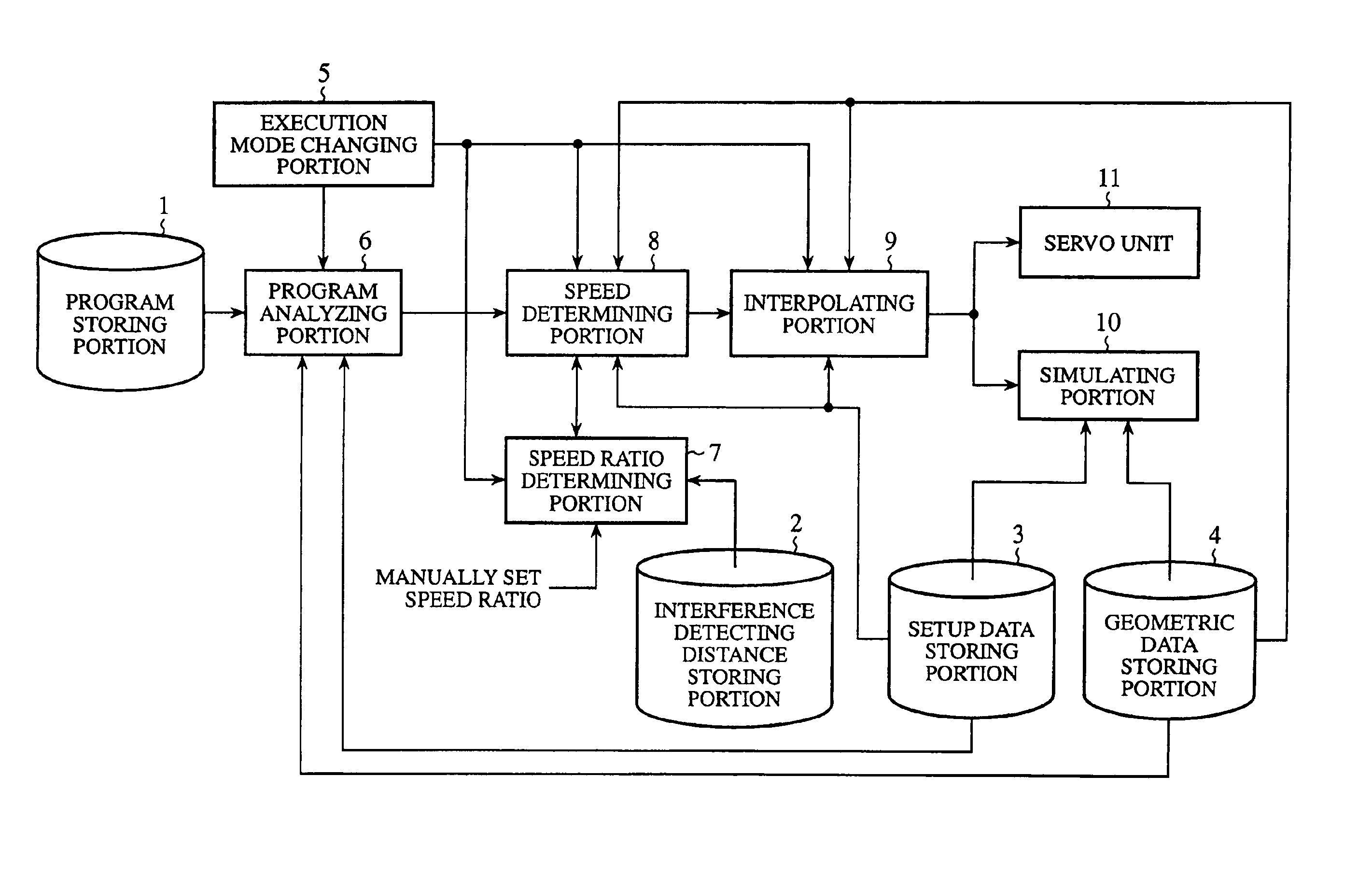
FIG. 1 is a block diagram showing a simulation device according to the first embodiment of the present invention.

Referring to FIG. 1, a program storing portion 1 stores an NC program or other programs for an automatic programming system described therein feeding speeds and positional instructions of an operative part, e.g., a robot's arm and foot, and a cutting tool (see FIG. 2). An interference detecting distance storing portion 2 stores interference detecting distances, e.g., the distance between an operative part A and an operative part B, the distance between the operative part A and a stationary part C, such as a main body or foundation of the machine. Moreover, a setup data storing portion 3 stores setup data of jig and work arrangements or the like. A geometric data storing portion 4 stores geometric data of the machine, geometric data of jigs, geometric data of tools, or the like in the virtual three-dimensional simulation space. In passing, the program storing portion 1, th...

second embodiment

While in the first embodiment, the execution mode changing portion 5 changes an execution mode between an actual machine operation mode and a simulation mode, the simulation device may be modified to a system dedicated to the simulation mode without implementing the execution mode changing portion 5 and the servo unit 11, as shown in FIG. 6.

In this way, the omission of capabilities incorporated in the simulation device permits arrangement of the simulation device outside the numerical control device. Accordingly, the actual machine operation and an interference check through a machine simulation can be independently performed at any given time, without stopping the actual machine operation for executing a simulation. Therefore, while machining a work on the actual machine by using an already checked NC program, a simulation can be executed concurrently to check an NC program for the next machining. This enhances the overall work efficiency ranging from program verification and an ac...

third embodiment

While in the first embodiment, the program analyzing portion 6, the speed ratio determining portion 7, the speed determining portion 8, and the interpolating portion 9 are provided by one system, each executing an operation either in a simulation mode or in an actual machine operation mode under the directions of the execution mode changing portion 5, it may be provided a processing line A (encircled area shaded by a slant line) exclusively dedicated to the simulation mode and a processing line B (encircled area indicated by a dotted line) exclusively devoted to an actual machine operation mode, as shown in FIG. 7.

In this way, such separate provision of the processing line A exclusively responsible for the simulation mode and the processing line B exclusively responsible for execution of the actual machine operation mode makes it possible to perform operating a simulation of the machine, even if the actual machine is in operation, using tool information, jig information, information...


PUM


Abstract

A simulation device is provided with a speed ratio determining portion and a speed determining portion for calculating the maximum feeding speed of an operative part from an interference detecting distance and an interpolation period, and replacing the feeding speed of the operative part, which is read out by a program analyzing portion, with the maximum feeding speed; and an interpolating portion for determining interpolated points of a moving path of the operative part from the feeding speed of the operative part, which is replaced by the maximum feeding speed by the speed ratio determining portion and the speed determining portion, and the interpolation period. An interference check on the operative part is made at an interpolated point determined by the interpolating portion.

Description

BACKGROUND OF THE INVENTION1. Field of the InventionThe present invention relates to a simulation device making an interference check on an operative part.2. Description of the Related ArtAn NC (numerical control) program (hereinafter, a unit of instructions described in an NC program is referred to as a block) is required to carry out machining by an existing numerical control (NC) machine tool. Generally, an NC program contains instructions to instruct a machine to move at a moving speed and numerical values representative of a specific moving speed.Recently, with an increasing complexity of structure of a machine tool, its operations are more complicated. For this reason, it is not seldom that a variety of portions of the machine can mutually interfere, and the machine and a target (hereinafter referred to as a work) can interfere with each other. Therefore, to avoid such unfavorable interference, the necessity for simulation of behavior of the machine is increasing, of which mai...

Claims


Application Information

Patent Timeline
IPC IPC(8): B23Q15/00G05B19/4068G05B19/4069G05B19/4061G05B19/406G06F19/00B25J9/16
CPCB25J9/1666G05B19/4069G05B2219/49143G05B2219/40454
Inventor TAKAHASHI, NOBUYUKITSUJIDO, YOSHINORIIRIGUCHI, KENJIOKADA, KIYOSHIKAMIYA, TAKASHI
Owner MITSUBISHI ELECTRIC CORP