Connecting method of pins and tin balls of an electric connector

Active Publication Date: 2005-02-22
ACCENTURE GLOBAL SERVICES GMBH
View PDF3 Cites 10 Cited by
  • Summary
  • Abstract
  • Description
  • Claims
  • Application Information

AI Technical Summary

Benefits of technology

Accordingly, the primary object of the present invention is to provide a connecting method of pins and tin balls of an electric connector, wherein pins of the electric connector resist against tin balls so as to position the pins; the lower ends of the pins store elastic energy due to the elastic resisting of the pins against the resisting contact. During welding by blowing, heated air, the elastic energy is released to push the melting tin balls so that the lower ends of the pins of the electric connector is tightly combined with the PC board. Thereby, the lower end of the pin is highly conductive to the PC board 2 and the yield ratio is improved.

Problems solved by technology

As a result, the function of the electric connector is not preferred and the yield ratio is low.

Method used


Image

  • Connecting method of pins and tin balls of an electric connector
  • Connecting method of pins and tin balls of an electric connector
  • Connecting method of pins and tin balls of an electric connector

Examples


first embodiment

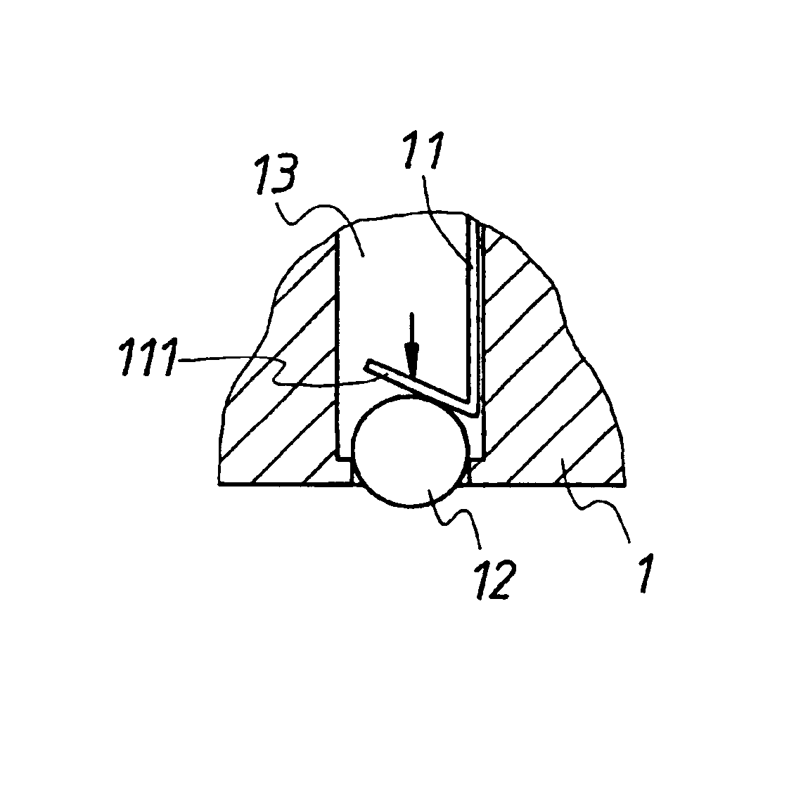
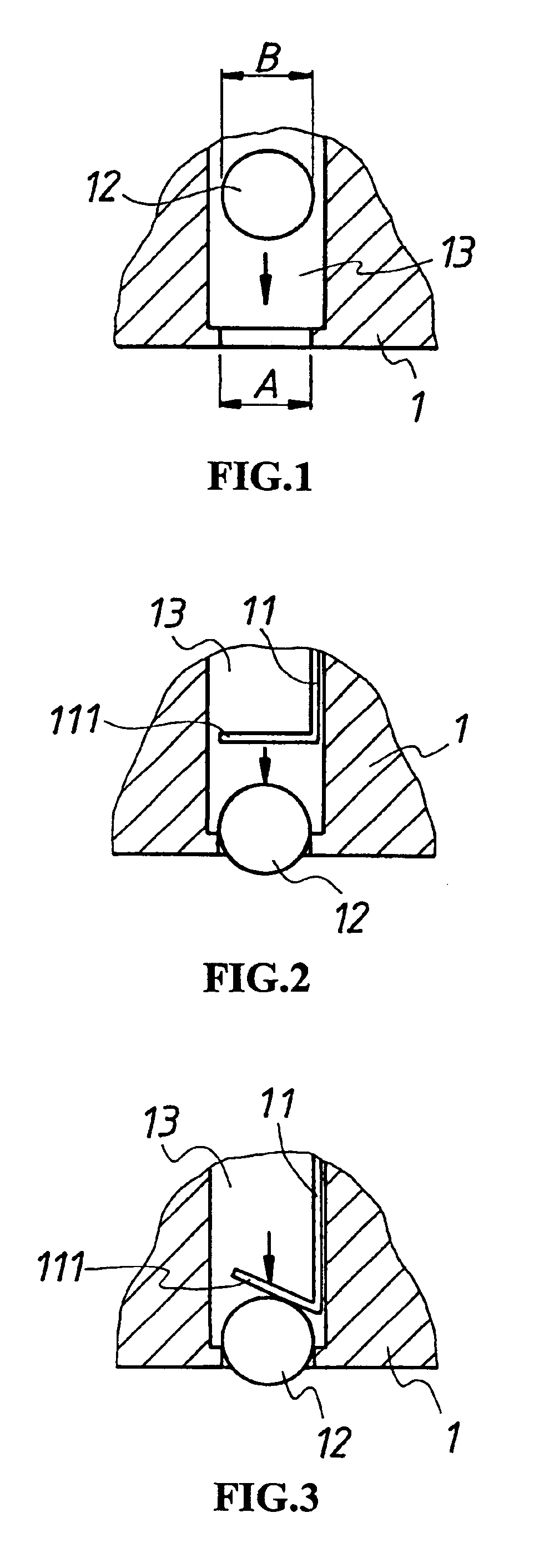
Referring to FIGS. 1 to 3, the present invention about the connecting method of pins and balls of an electric connector of the present invention is illustrated. Before welding the electric connector 1 and the PC board 2 by blowing heated air, the tin balls 12 are preinstalled in a plurality of receiving holes 13 one by one. A distal end of each receiving hole 13 has a diameter A smaller than the diameter B of the tin ball 12 so that after the tin ball 12 has been placed in the receiving hole 13, it is buckled therein (referring to FIG. 2) and part of the tin ball 12 exposes out of the receiving hole 13. Then the pins 11 of the electric connector 1 are placed therein one by one so that the lower end 111 of the pin 11 resists against the tin ball 12 and is positioned thereagainst. A lower end 111 of the pin 11 resists against the tin ball 12 and thus it is bent and deformed so as to store elastic energy (referring to FIG. 3).

second embodiment

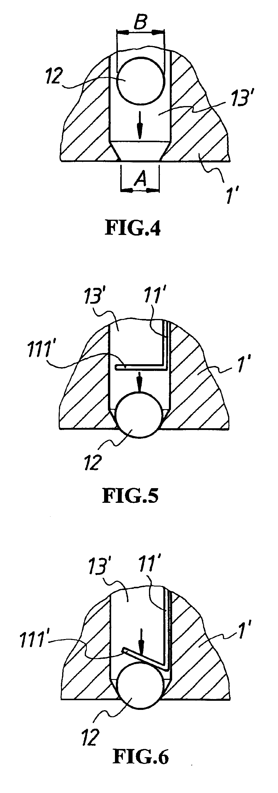
Likewise, referring to FIGS. 4 to 6, the present invention is illustrated. In about electric connector 1′, each of the plurality of receiving holes 13′ has distal end with a hole diameter A′. The hole at the distal end is a tapered hole. Thereby, the diameter A′ must smaller than the diameter B′ of the tin ball 12 so that when the tin ball 12 is placed in the receiving hole 13′, it can be buckled therein (referring to FIG. 5). The receiving hole 13′ has a part being exposed. Then the pins 11′ of the electric connector 1 is embedded one by one so that the lower ends 111′ of the pins 11′ resists against the tin ball 12 and are positioned therein. Since the lower ends 111′ of the pins 11′ resists against tin balls 12 and thus they are deformed and thus elastic energy is stored (referring to FIG. 6).

According to above first or second embodiment, each pin 11(11′) resists against the tin ball 12 so as to store elastic energy. Thereby, in welding, the elastic energy stored in the pins will...

third embodiment

In above embodiment, as illustrated in FIG. 8, the electric connector 1 is arranged as an array. For another example illustrated in FIG. 9, the electric connector 1 has a plurality of pins 31 which is embedded therein and parts of the pins are exposed. Thereby, in the present invention, the electric connector 1 has a transversal unit 32 at position below the plurality of pins 31. The transversal unit 32 is formed with a plurality of tin ball implanting holes (referring to FIGS. 10 and 11) with respect to the pins 31. A distal end of each tin ball planting hole 321 has a hole diameter C slightly smaller than the diameter B of the tin ball 12. Thereby, the tin ball 12 can be placed into the tin ball planting hole 321 to be tightly engaged therein and part of the tin ball 12 is exposed from the tin ball receiving hole 321 so that the lower end 111 of each pin 31 of the electric connector 1 exactly resists against the tin ball 12 and is positioned thereupon. Because of the elastic resis...


PUM

PropertyMeasurementUnit
Diameteraaaaaaaaaa
Energyaaaaaaaaaa

Abstract

A connecting method for pins and tin balls of an electric connector. Pins of the electric connector elastically resist against tin balls so as to position the pins. The lower ends of the pins store elastic energy due to the elastically resisting contact. During welding by blowing heated air, the elastic energy is released to push the melting tin balls so that the lower ends of the pins of the electric connector is tightly combined with the PC board.

Description

BACKGROUND OF THE INVENTION(a) Field of the InventionThe present invention relates to electric connectors, and particularly to a connecting method of pins and tin balls of an electric connector, wherein a plurality of pins of the electric connector resist against tin balls so as to position the pins; the lower ends of the pins store elastic energy due to the resisting contact. Thereby, the lower end of the pin is well conductive to a PC board and the yield.(b) Description of the Prior ArtReferring to FIGS. 16 to 18, the prior art connecting way of pins of electric connector and tin balls are illustrated. A layer of weld-assisting agent is coated at a lower end 101 of the pin 10 of an electric connector so as to combine the tin ball 30 to the lower end 101 of the pin 10. Then, the PC board 40 is welded with the electric connector by blowing heated air and thus the tin ball 30 is melted and welded to a lower end of the pin 101 and the joint 401 of the PC board. With reference to FIG. ...

Claims


Application Information

Patent Timeline
IPC IPC(8): H01R43/02H05K3/34
CPCH01R43/0256H05K3/3426H01R43/0263Y10T29/49208Y10T29/49211Y10T29/4921Y10T29/49218Y10T29/49217Y02P70/50
Inventor JU, TED
Owner ACCENTURE GLOBAL SERVICES GMBH
Why Eureka
Try Eureka