Airflow driven electrical generator for a moving vehicle

a technology for electric generators and moving vehicles, applied in wind motors with parallel air flow, wind power generation, gas pressure propulsion mountings, etc., can solve the problems of generating significant drag, consuming more energy than is gained, and generating significant drag, etc., to achieve low drag and high efficiency

Inactive Publication Date: 2005-02-22
LISKEY KENNETH W +1
View PDF22 Cites 123 Cited by
  • Summary
  • Abstract
  • Description
  • Claims
  • Application Information

AI Technical Summary

Benefits of technology

The present invention provides various advantages over what has been done in the past including the providing of a high efficiency, low drag system which may be utilized on vehicles travelling at all speeds, from low speeds to high speeds.

Problems solved by technology

However, such propellers generate significant drag, and particularly at higher speeds, the drag can use more energy than is gained by the electrical generation system.
Although Hakala uses two different impeller blades, he still uses impeller blades which produce significant drag.

Method used


Image

  • Airflow driven electrical generator for a moving vehicle
  • Airflow driven electrical generator for a moving vehicle
  • Airflow driven electrical generator for a moving vehicle

Examples


Embodiment Construction

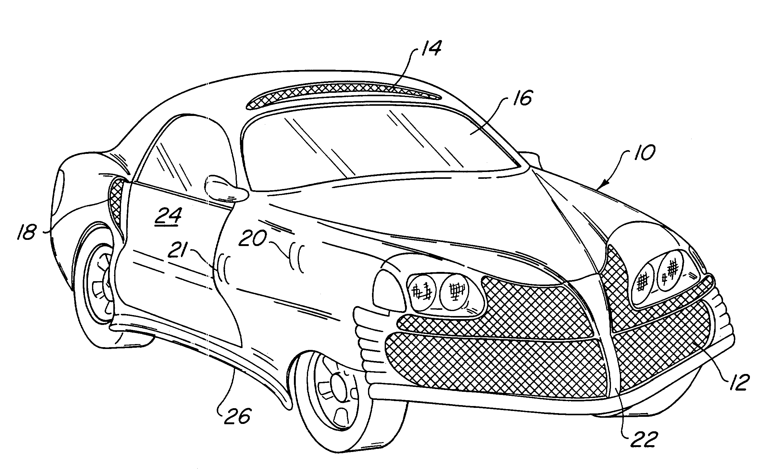
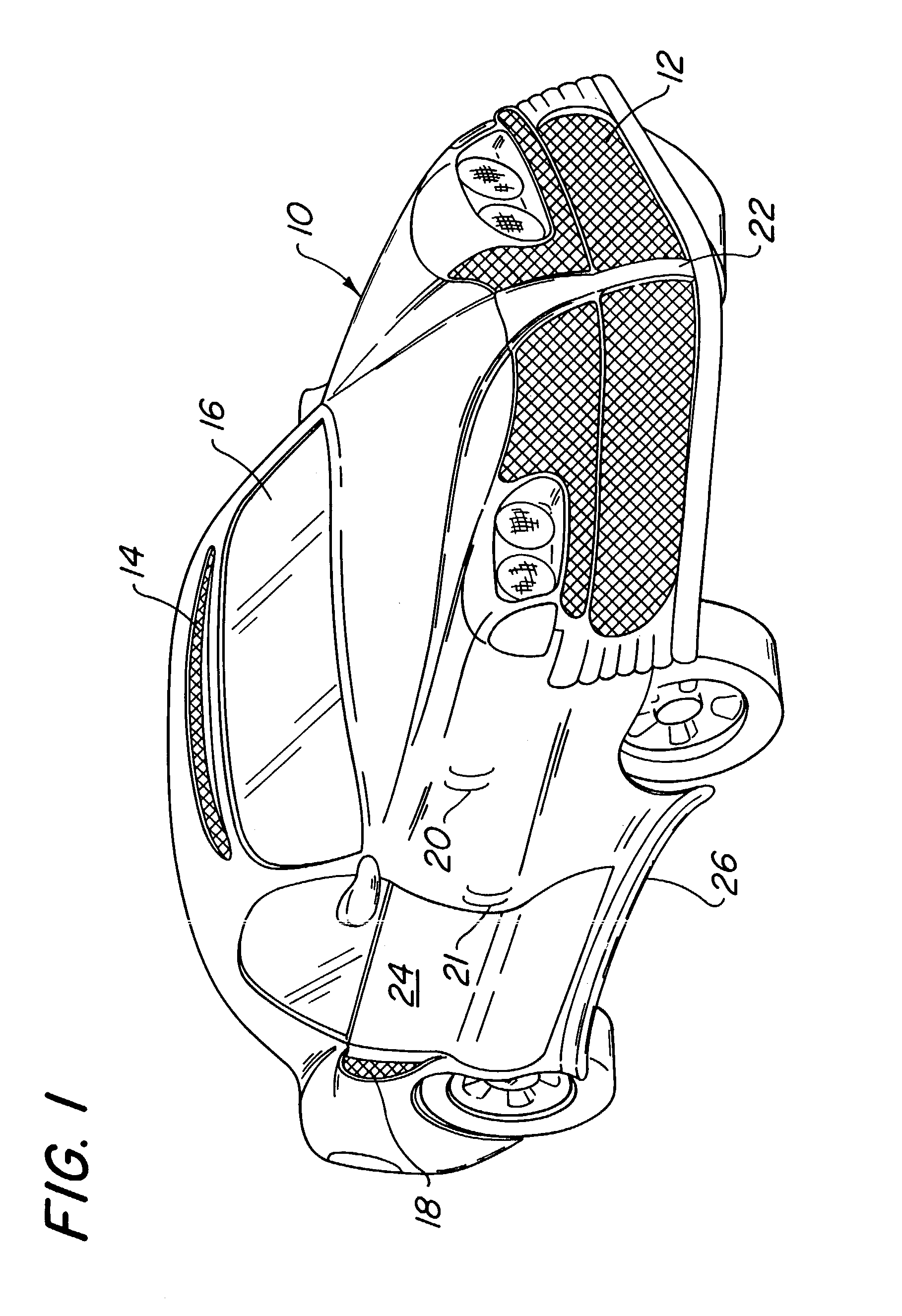
Referring now to the drawings in detail, wherein like numerals indicate like elements, there is shown in FIG. 1 a motor vehicle 10 in the form of an automobile. Motor vehicle 10 may be provided with a front grill 12 for the collection of air as the vehicle move forward through the atmosphere. Grill 12, as well as other grills on the vehicle, may be provided with or act as a filter to prevent particles, such as road debris, bugs and the like, from entering the airflow system of the vehicle. Further, particularly where a vehicle may be operated in cold wet conditions, grill 12 and the other grills utilized on the intakes at collection sites may be provided with heaters to prevent icing from occurring in the airflow channels such as the vents and airflow passages of the generator. Additional collection sites may be formed on the vehicle. As illustrated in FIG. 1, collection site 14 may be provided in the roof area above the windshield. The motor vehicle 10 may be aerodynamically desig...


PUM


Abstract

An apparatus for generating electricity in a moving vehicle utilizes a low drag spirally shaped fin mounted longitudinally on a cylindrical component of a generator which receives air from a vent as the vehicle moves through air. The vent includes structure for bypassing at least a portion of the airflow through the vent as the vehicle moves faster through the air. The airflow causes the cylindrical member to rotate causing the generator to generate electricity. The rotating cylindrical member may be provided with magnetic material.

Description

FIELD OF THE INVENTION The present invention relates to an airflow driven electrical generator for a moving vehicle. More particularly, the present invention relates to an airflow driven electrical generator for a moving vehicle which provides increased efficiency and reduced drag. BACKGROUND OF THE INVENTION Efficient and cost effective transportation by a vehicle, whether by motor vehicle, train, airplane or boat, has become very important. Conserving energy and achieving the maximum benefit from the energy available is very important in achieving these goals. There has been some significant effort in recent years to produce an effective electrically powered automotive vehicle. There is a desire for such electric vehicles to be efficient and to maximize the possible trip milage available before recharging of batteries and the like. There has been a desire to be able to produce electrical energy for use in a vehicle and for storage of energy for future use in the vehicle. One effor...

Claims


Application Information

Patent Timeline
Patent Type & Authority Patents(United States)
IPC IPC(8): B60L8/00B60K16/00B63J3/00B63J3/04B64D41/00H02J7/14F03D11/04
CPCB60K16/00B63J3/04B64D41/007F03D9/002F03D11/04B60L8/006B60L2200/26B63J2003/046F05B2240/941F05B2250/25H02J7/1415Y02E10/728Y02T10/7083Y02T10/90Y02T70/70Y02E10/725B60L2200/10B60L2200/32B60K2016/006F03D13/20F03D9/25H02J2310/44H02J2310/42F03D1/02F03D1/04F03D9/32Y02E10/72Y02T10/7072Y02T70/00
Inventor LISKEY, KENNETH W.LISKEY, EUGENE B.
Owner LISKEY KENNETH W
Why Eureka
Try Eureka