Engine muffler and method of manufacturing the same

a technology of engine mufflers and mufflers, which is applied in the field of mufflers, can solve the problems of reducing the sound muffling ability, affecting the sound absorbing ability, and affecting the sound absorbing ability, and achieves the effects of low cost, simple structure and easy manufacturing

Inactive Publication Date: 2005-02-22
SANKEI GIKEN KOGYO
View PDF16 Cites 27 Cited by
  • Summary
  • Abstract
  • Description
  • Claims
  • Application Information

AI Technical Summary

Benefits of technology

With such circumstanced in view, it is an object of the present invention to provide a durable and easy-to-manufacture engine muffler by securing the sound absorbing material reliably during use or during manufacturing process, and a method of manufacturing the same.
The advantages offered by the engine muffler and the method of manufacturing the same according to the present invention are mainly that leaning of the sound absorbing material to one end or occurrence of wrinkles thereon due to slippage thereof during manufacturing or usage of the muffler can be prevented only by a very simple structure, or by simply providing a projection projecting toward the sound absorbing material on the external tube. Therefore, this type of muffler can be manufactured easily at low cost, and lowering of sound eliminating capability or durability can preferably be prevented.

Problems solved by technology

However, in the muffler described above, the sound absorbing material may lean to one side or be deformed after long time of use due to vibration of the vehicle body, vibration of the engine, or expansion and contraction caused by exhaust heat.
Especially, when the axial length of the sound absorbing material interposed between the external and the internal tubes is long, it tends to lean to one side, and when different types of sound absorbing materials multilayered in the direction of thickness tend to be subject to slippage or wrinkles at the mating portion.
As a consequent, the sound absorbing material may vary in bulk density and thus lower the sound-muffling capability, or may scatter and thus lowering the durability disadvantageously.
However, when the diameter of the tapered end decreases, the structure of the jig becomes complex, and there may be cases where it cannot be secured by a jig.

Method used


Image

  • Engine muffler and method of manufacturing the same
  • Engine muffler and method of manufacturing the same
  • Engine muffler and method of manufacturing the same

Examples


Embodiment Construction

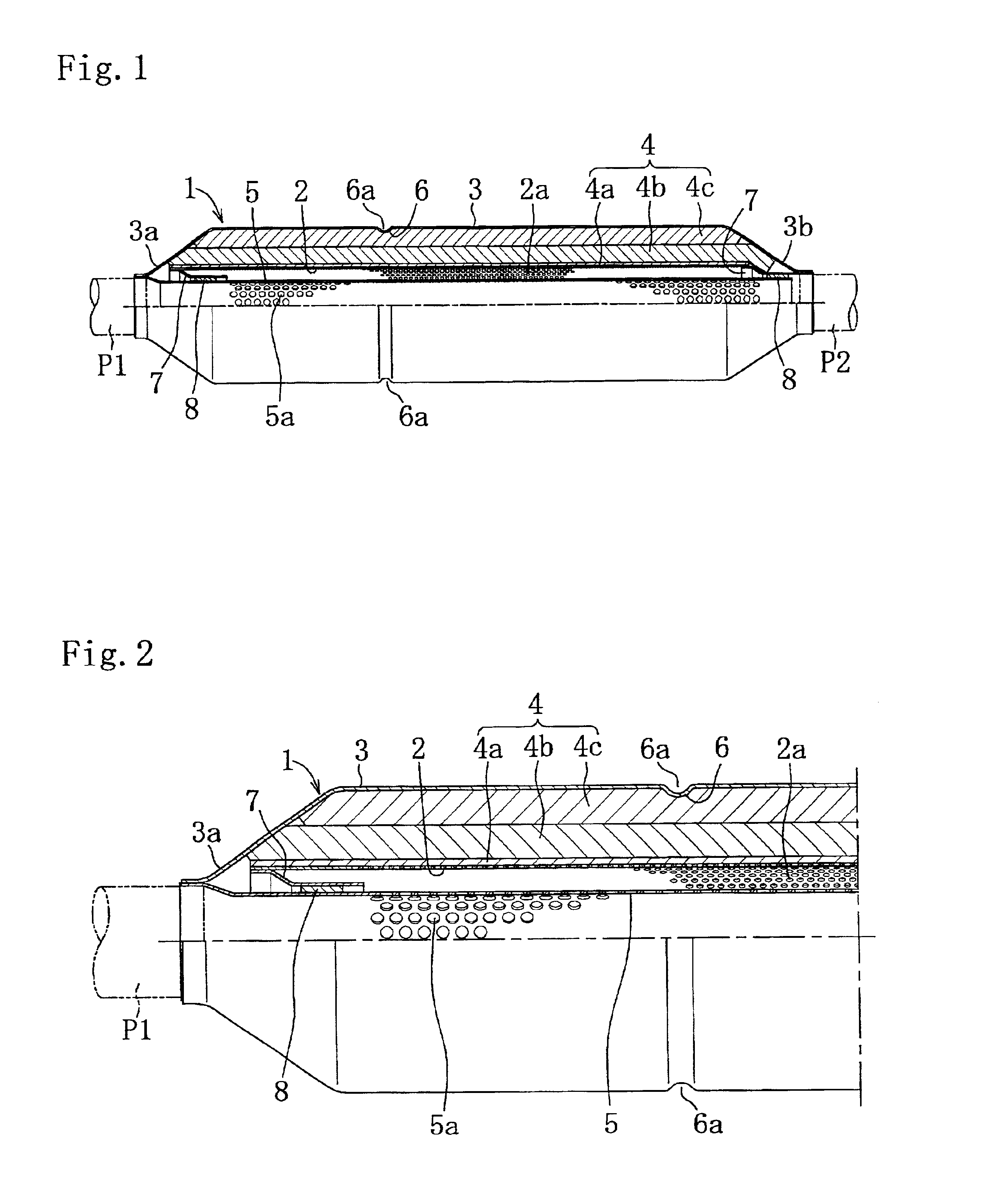
An engine muffler and a method of manufacturing the same according to the present invention will be described in detail referring to the embodiment shown in the figures.

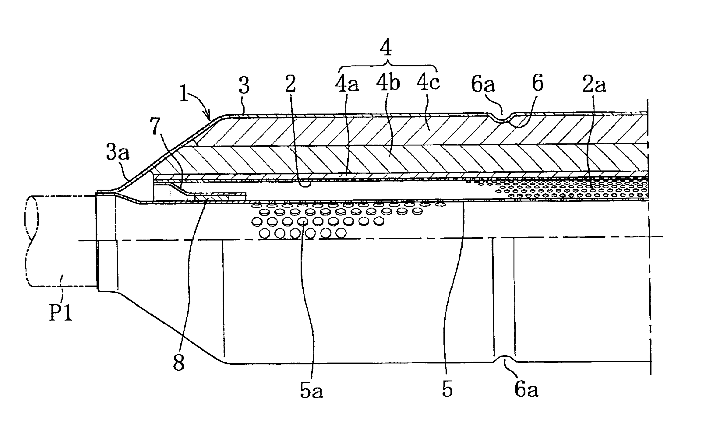
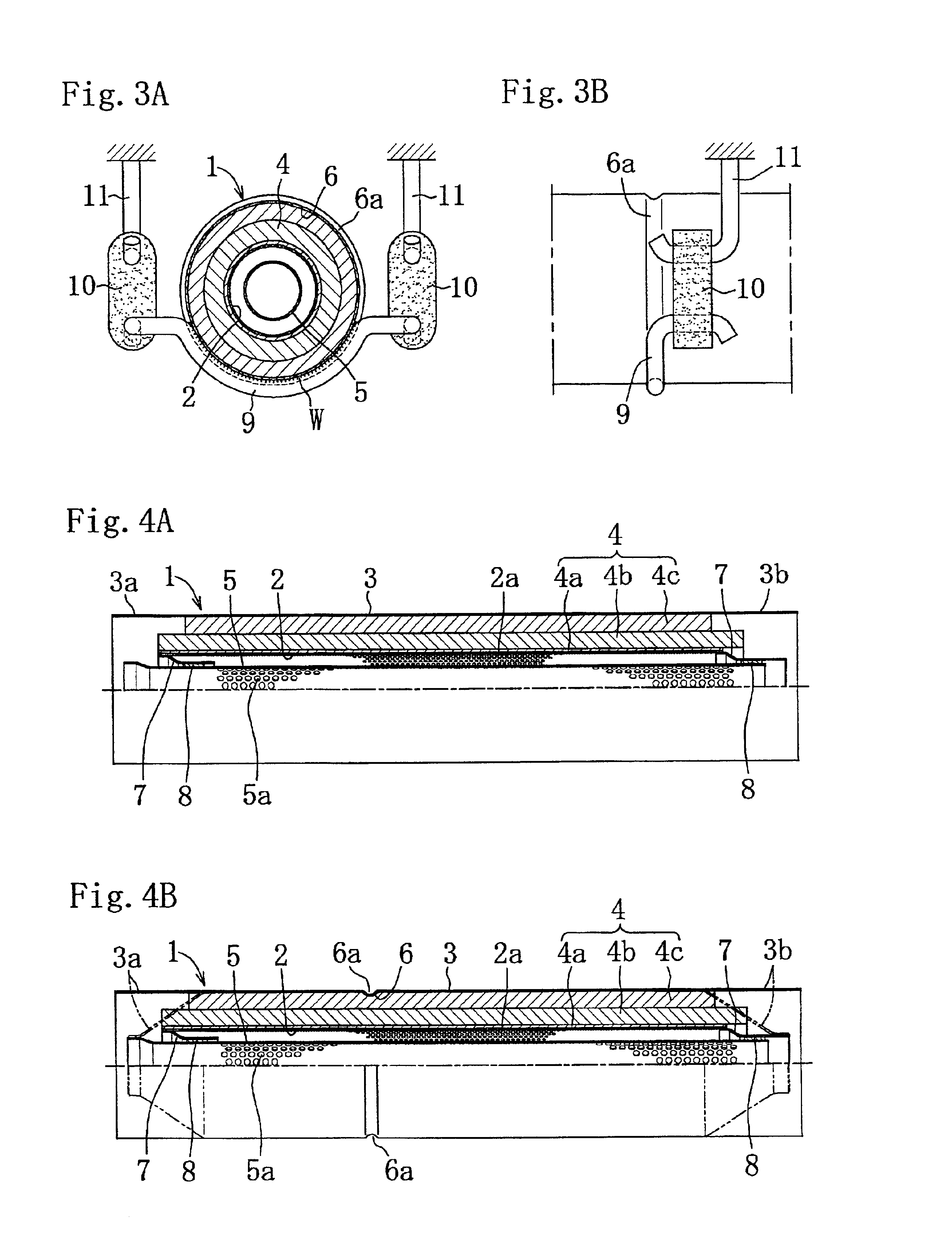
In this embodiment, the present invention is applied to the sub-muffler to be disposed immediately behind the catalytic converter that is disposed relatively upstream of the engine exhaust system for automobiles. Referring now to FIG. 1 and FIG. 2, the muffler 1 comprises a sound absorbing material 4 interposed between the internal tube 2 and the external tube 3 and an exhaust air guiding tube 5 provided inside the internal tube 2.

The sound absorbing material 4 is formed of a plurality of kinds of sound absorbing materials 4a-4c having different properties in heat-resistance and sound absorbing capability multilayered in the direction of thickness. In the case shown in the figure, a sound absorbing material 4a formed of a heat-resisting material such as stainless wool is arranged on the outer periphery of the interna...


PUM

PropertyMeasurementUnit
heat resisting propertiesaaaaaaaaaa
thicknessaaaaaaaaaa
axial lengthaaaaaaaaaa

Abstract

This engine muffler has a sound absorbing material interposed between an internal tube and an external tube which is formed with a projection projecting toward the sound absorbing material along almost its entire periphery. When interposing the sound absorbing material between the internal tube and the external tube and drawing the end of the external tube for manufacturing the muffler, the projection projecting toward the sound absorbing material is formed on the external tube almost along its entire periphery after inserting the sound absorbing material between the internal tube and the external tube but before drawing the end of the external tube.

Description

BACKGROUND OF THE INVENTION1. Field of the InventionThe present invention relates to a muffler to be used for the exhaust system of an engine, for example, for automobiles, and a method of manufacturing the same.2. Description of the Related ArtHitherto, a muffler to be used for the exhaust system of an engine for automobiles or the like such as a sub muffler to be disposed immediately behind the catalytic converter, a main muffler to be placed at the rear of the exhaust system, or a sound absorbing muffler to be disposed in the main muffler, having a sound absorbing material interposed between the internal tube and the external tube is known.However, in the muffler described above, the sound absorbing material may lean to one side or be deformed after long time of use due to vibration of the vehicle body, vibration of the engine, or expansion and contraction caused by exhaust heat. Especially, when the axial length of the sound absorbing material interposed between the external and...

Claims


Application Information

Patent Timeline
Patent Type & Authority Patents(United States)
IPC IPC(8): F01N1/24F01N7/18F01N1/02F01N1/04F01N13/00F01N13/18F01N99/00
CPCF01N1/24F01N13/148F01N13/18F01N13/1822F01N2310/02Y10T29/49398F01N2450/06F01N2450/22F01N2470/04F01N2470/24F01N2470/26F01N2310/04
Inventor NAITO, TAKAHIKO
Owner SANKEI GIKEN KOGYO
Why Eureka
Try Eureka