Current limit engagement apparatus

Inactive Publication Date: 2005-02-22
HEWLETT PACKARD DEV CO LP
View PDF7 Cites 27 Cited by
  • Summary
  • Abstract
  • Description
  • Claims
  • Application Information

AI Technical Summary

Benefits of technology

An electrical connector is constructed with at least one pin configured to provide different resistance values as the pin is engaged with a socket. When the connector is fully engaged with the socket the resistance of the connector is at a zero or minimal value. When the pin first contacts the socket, the pin includes a high series

Problems solved by technology

If due to space (or other) constraints, the pins are not designed for an individual pin to handle the full normal operating current, there is a high probability of damage to the pins or the socket from arcing, overheating, or stress from the instant flow of full current.
It is also possible that there will exist a safety hazard since many connectors designed to handle high currents have exposed metal parts allowing people to receive electric shocks or burns.
Some designs include resistors in series with the capacitors to act as current limiters, however, it is only necessary to limit current to the ca

Method used


Image

  • Current limit engagement apparatus
  • Current limit engagement apparatus
  • Current limit engagement apparatus

Examples


Embodiment Construction

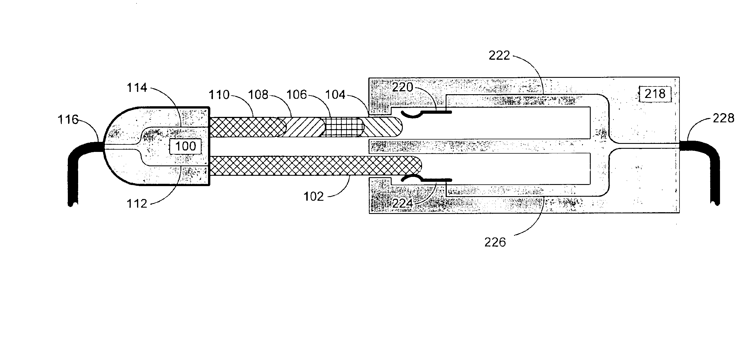
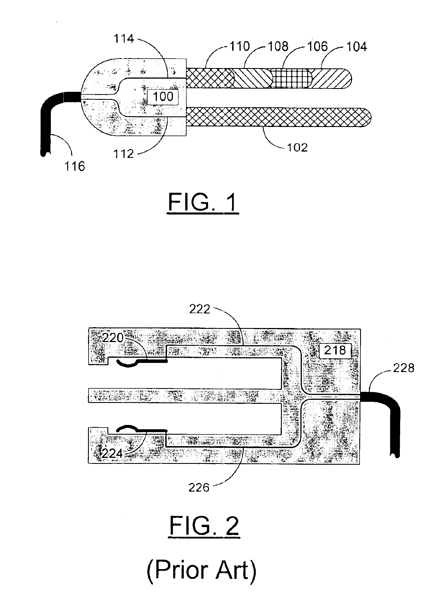
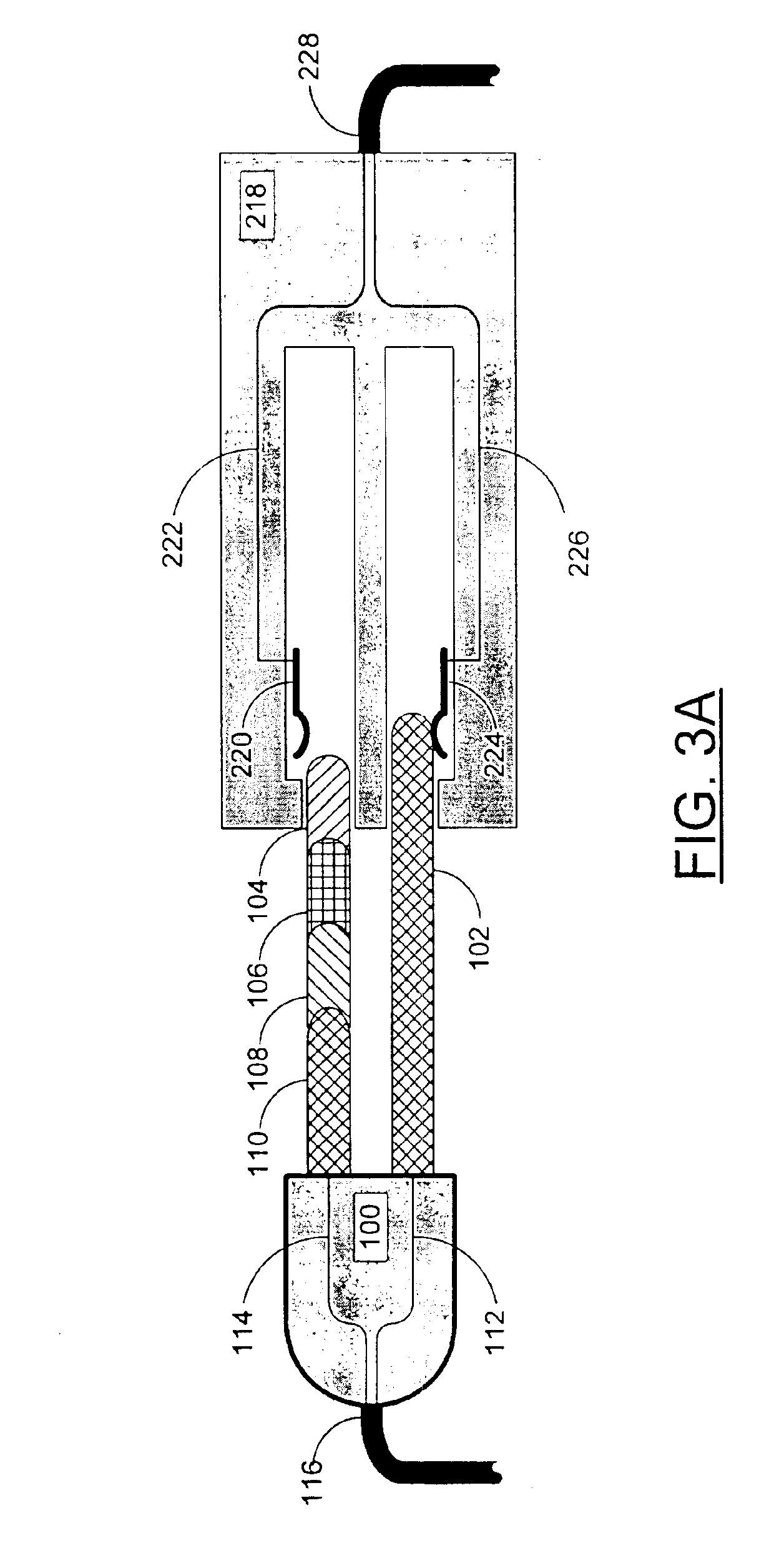
FIG. 1 is a side view of an example embodiment of a current limit engagement apparatus according to the present invention. In this example embodiment of the present invention a two-pronged power plug is shown including a plug body 100, a ground conductor 112, a power conductor 114, a cable 116 for connecting the plug to an electric device, a ground pin 102, and a power pin including a current limiting apparatus. Note that in this example embodiment of the present invention, the ground pin 102 is longer than the power pin. This allows the ground pin to make first connection with a mating socket before the power pin starts to make a connection. In this example embodiment of the present invention the power pin includes a first segment 104, with a high series resistive value to limit the initial inrush of current to the electric device, a second segment 106, with a lower resistive value than the first segment 104, a third segment 108, with a lower resistive value than the second segment...


PUM


Abstract

An electrical connector is constructed with at least one pin configured to provide different resistance values as the pin is engaged with a socket. When the connector is fully engaged with the socket the resistance of the connector is at a zero or minimal value. When the pin first contacts the socket, the pin includes a high series resistance minimizing the sudden inrush of current to an electrical device, and minimizing any arcing between the pin and the socket. As the pin engages the socket this series resistance decreases allowing the electronic device to utilize its full designed current with only minimal contact resistance between the pin and the socket.

Description

FIELD OF THE INVENTIONThis invention is related to the field of electrical connectors, and more specifically to the field of electrical connectors designed to reduce current inrush peaks during plug in.BACKGROUND OF THE INVENTIONWhen an electronic device is plugged in or turned on in an AC or DC electrical circuit, the electric plug's male and female connections come together and high current immediately begins to flow through the pins. Once any contact (and sometimes before contact if an arc occurs) is made on the pins, fill normal operating current flows through the device. Thus, in many electronic devices the pins are designed so that any part of the pins or socket can immediately handle the full normal operating current. If due to space (or other) constraints, the pins are not designed for an individual pin to handle the full normal operating current, there is a high probability of damage to the pins or the socket from arcing, overheating, or stress from the instant flow of full...

Claims


Application Information

Patent Timeline
IPC IPC(8): H01R13/66
CPCH01R13/6616
Inventor BELSON, STEVELORBER, WALTER G.
Owner HEWLETT PACKARD DEV CO LP
Why Eureka
Try Eureka