
Method for deactivating a marine alternator during periods of high engine power requirements

a marine alternator and engine power technology, applied in marine propulsion, vessel auxiliary drives, vessel construction, etc., can solve the problems of large engine power requirements, large capacity of small alternators, and inability to provide as much of their total power to the function of propelling marine vessels

Active Publication Date: 2005-02-22
BRUNSWICK CORPORATION
View PDF10 Cites 9 Cited by
  • Summary
  • Abstract
  • Description
  • Claims
  • Application Information

AI Technical Summary

Benefits of technology

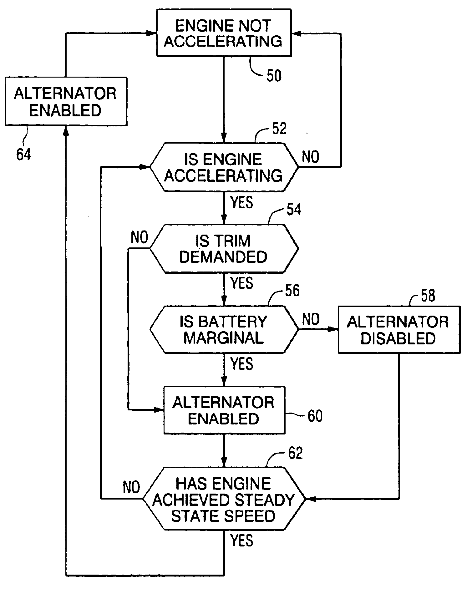
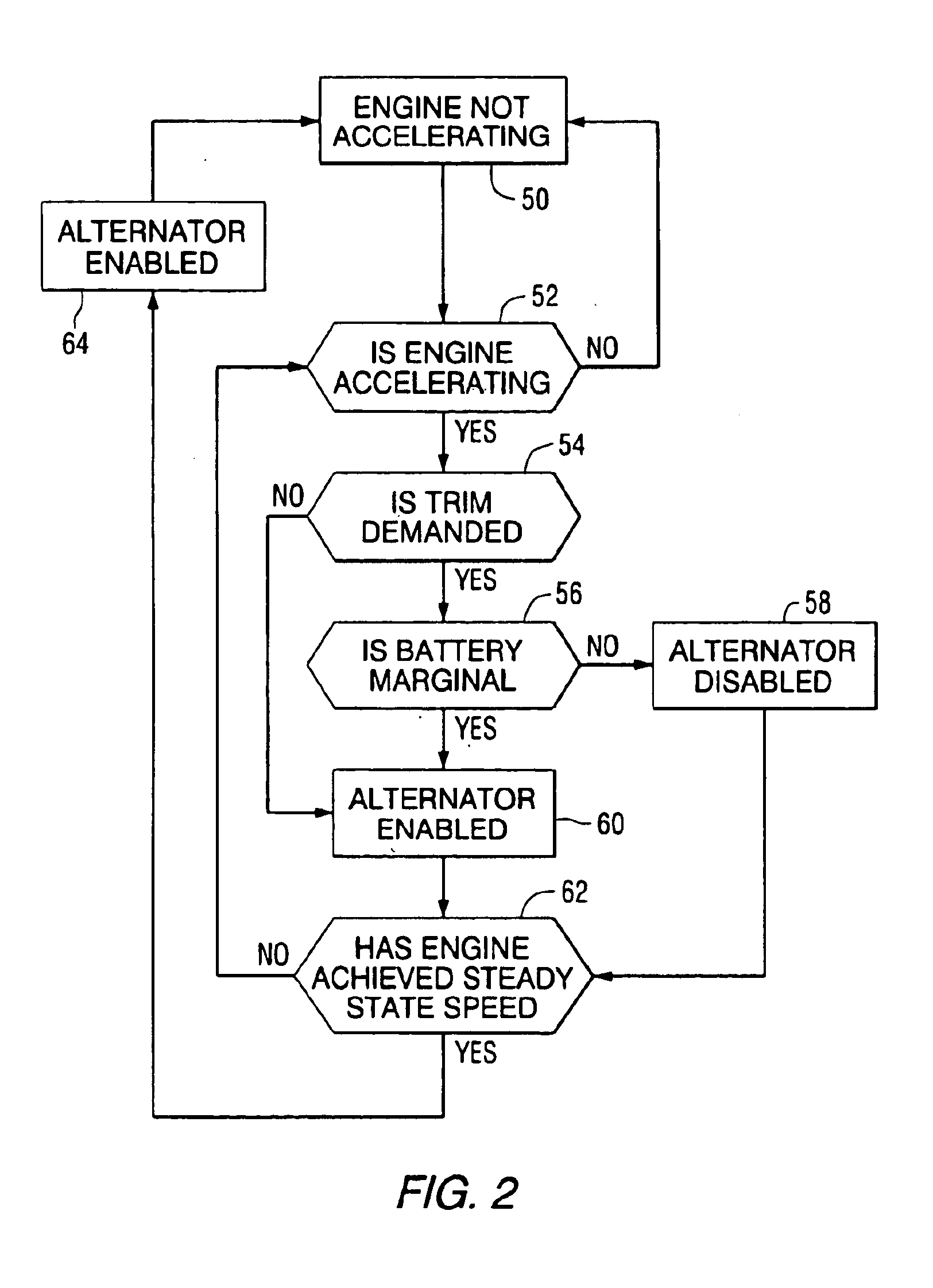
A preferred embodiment of the present invention can further comprise the step of providing a trim adjusting mechanism to change the relative position of the marine propulsion system in relation to the marine vessel and performing the deactivating step regardless of the relative magnitude of the operating characteristic and the preselected magnitude whenever the trim adjusting mechanism is activated and a signal to represent a timming operation. In other words, certain applications of the present invention can deactivate the alternator in every instance when the trim operation is commanded by the operator of the marine vessel. Although this is not preferred in every application of the present invention, it can achieve the similar goal even if the rate of acceleration of the engine is disregarded.

Problems solved by technology

Since the alternator requires mechanical power provided by the engine, the engine is unable to provide as much of its total power to the function of propelling a marine vessel as could otherwise be possibly if the alternator loads were removed.
Unlike alternators normally used in automotive applications, marine alternators are small, compact, and generally incapable of supplying all of the energy necessary to accommodate large power, short duration, electrical loads such as the trimming operation used to change the attitude of a marine propulsion system relative to its marine vessel.
This often exceeds the capability of the small alternator's output and the battery's power is used to satisfy the balance of this electrical requirement.
However, the alternator continues to require mechanical power from the engine in known marine propulsion systems.
This, in turn, provides an additional load on the engine which deprives the engine from the ability from providing maximum power to the propeller shaft in order to achieve the required acceleration in a minimum time.

Method used


Image

  • Method for deactivating a marine alternator during periods of high engine power requirements
  • Method for deactivating a marine alternator during periods of high engine power requirements
  • Method for deactivating a marine alternator during periods of high engine power requirements

Examples


Embodiment Construction

Throughout the description of the preferred embodiment of the present invention, like components will be identified by like reference numerals.

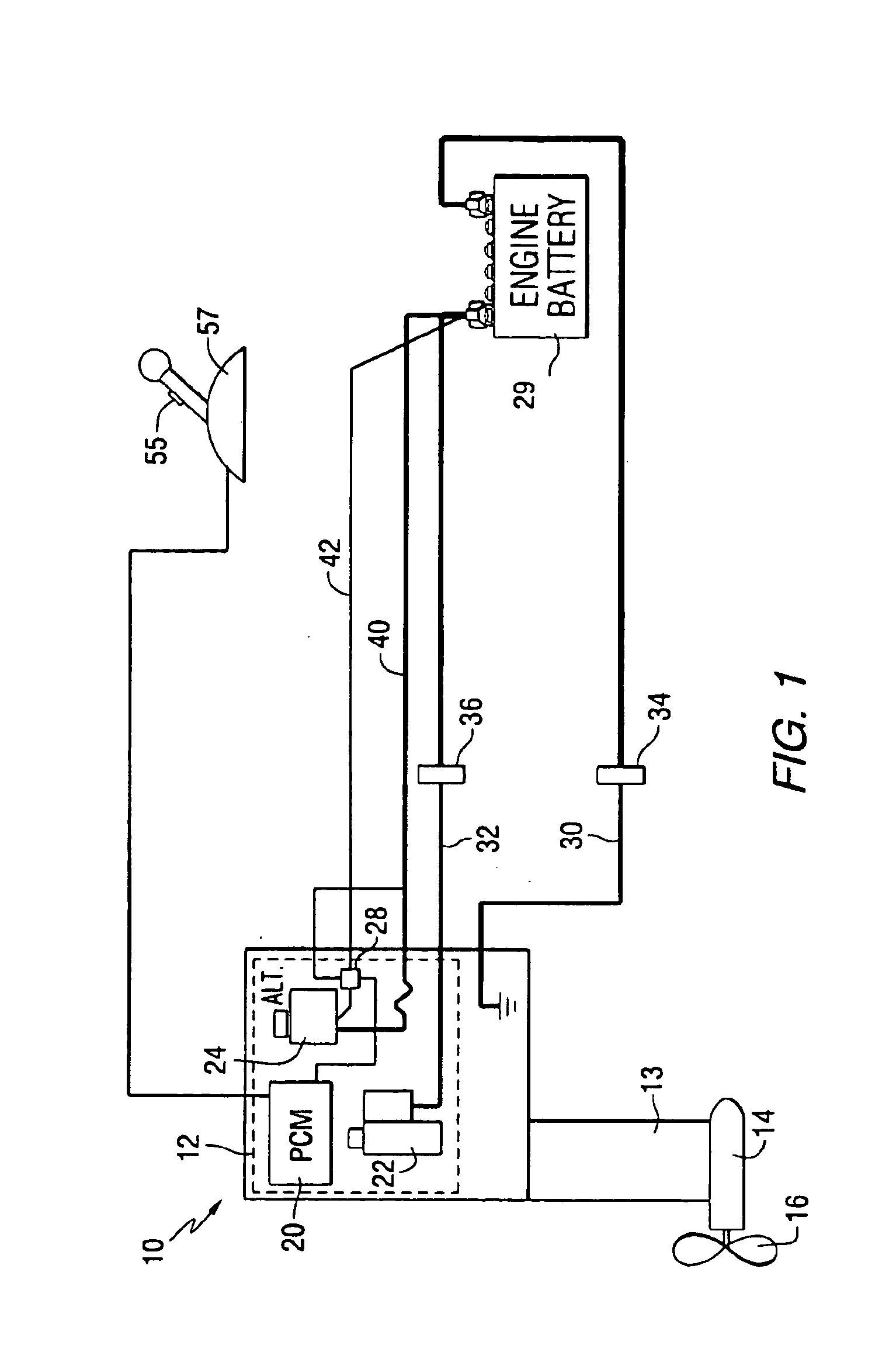
FIG. 1 is a highly schematic representation of an outboard motor 10 which contains an engine 12, represented by dashed lines, a driveshaft housing 13, a gearcase 14 which houses a propeller shaft, and a propeller 16 which is attached to the propeller shaft for rotation relative to the gearcase 14. Also contained within the outboard motor 10 is a propulsion control module (PCM) 20, a starter motor 22, an alternator 24, and a control relay 28. It should be understood that the components of the outboard motor 10 are not all shown in their accurate positions relative to the engine 12, but the typical arrangement of the starter motor and alternator are well known to those skilled in the art. Generally, the alternator is driven by the crankshaft of the engine 12, either with a belt and pulley arrangement or a gear mesh relationship. Several connect...


PUM


Abstract

A method is provided for controlling the operation of the alternator in such a way that during certain conditions, such as rapid acceleration of a marine vessel in combination with a trimming maneuver, the alternator of the marine propulsion system is deactivated so that it does not provide a mechanical load on the engine during the accelerating maneuvers. This allows the engine to provide more power to the propeller and achieve the desired operating speed commanded by the operator of a marine vessel.

Description

BACKGROUND OF THE INVENTION1. Field of the InventionThe present invention is generally related to an operation of an alternator associated with the marine propulsion system and, more particularly, to a method for controlling the alternator in such a way that it does not decrease the power that can be provided by an internal combustion engine during certain modes of operation of a marine vessel.2. Description of the Prior ArtThose skilled in the art of marine propulsion engines and electrical systems used with those engines are familiar with many types of alternators and associated circuits.U.S. Pat. No. 4,111,174, which issued to Fitzner et al on Sep. 5, 1978, discloses an ignition system with an idle speed governor apparatus. An alternator driven capacitive discharge ignition system includes a tachometer circuit monitoring the speed-dependent repetition rate of discharge at an internal trigger power supply, the tachometer circuit causing the triggering threshold bias to be reduced ...

Claims


Application Information

Patent Timeline
IPC IPC(8): B63H21/00B63J3/00B63J3/04B63H21/22H02J7/14
CPCB63H21/213H02J7/1446B63J3/04H02J2310/42
Inventor WASILEWSKI, KURT J.
Owner BRUNSWICK CORPORATION
Learn More