Filtration vessel and method for rotary gas compressor system

a technology of rotary compressor and filtration vessel, which is applied in the direction of machine/engine, liquid fuel engine, separation process, etc., can solve the problems of excessive and continuous loss of lube oil, difficult particular applications, and high maintenance costs, and achieves the effect of convenient separation of bulk liquid and more uniform gas flow

Inactive Publication Date: 2005-02-22
PARKER INTANGIBLES LLC
View PDF28 Cites 26 Cited by
  • Summary
  • Abstract
  • Description
  • Claims
  • Application Information

AI Technical Summary

Benefits of technology

The filtration vessel of the invention is used with a rotary screw compressor for receiving a compressed liquid / gas mixture discharged from the compressor and for creating an essentially liquid free gaseous discharge stream. The filtration vessel of the invention is installed downstream of the compressor to reclaim or catch lube oil and to coalesce and remove lube oil aerosols generated from the shear forces produced in the compressor. Once the lube oil is caught it is stored in a sump within the filtration vessel for a short time and is then pumped back into the compressor for another cycle. The vessel includes a vertically arranged vessel housing having an inlet. A vortex knockout region is located within a lower region of the vessel housing and communicates with the vessel inlet. The vortex knockout region utilizes uniform circular motion to impose a centrifugal force on gas and liquid fluids entering the vessel housing. The centrifugal force acts to separate relatively heavier fluids from relatively lighter fluids. A vertically arranged down-comer pipe is centrally located within the vessel housing. A coalescer region is located above the vortex knockout region within the vessel housing and contains a plurality of coalescer filter elements. The coalescer element region communicates with the vortex knockout region by means of the down-comer pipe for receiving the relatively lighter fluids separated in the vortex knockout region and for separating any entrained liquids remaining in the fluids. An outlet from the vessel housing receives and discharges the filtered fluids.
Preferably, the vessel housing has generally cylindrical interior sidewalls. The down-comer pipe has a generally cylindrical exterior and is located generally along a vertical center line of the vessel housing. The cylindrical sidewalls of the vessel housing and the exterior of the down-comer pipe serve to create the centrifugal force which is exerted on fluids entering the vessel housing. The preferred down-comer pipe has a stepped design which facilitates separation of bulk liquid from gas in the fluids entering the vessel housing.
The preferred coalescer filter elements each comprise a porous media, each element being housed within a rigid, vertical housing. Each rigid vertical housing is preferably a metal cylinder having a length and an internal diameter for receiving the porous coalescer element. The metal cylinders have louvered holes along the entire lengths thereof, whereby each coalescer element housing acts as a gas flow conditioner by stabilizing the gas flow around the coalescer element contained therein. The louvered holes provided along the length of each coalescer element housing provide a slight back pressure on the fluid exiting the coalescer elements, thereby resulting in a more uniform gas flow.

Problems solved by technology

These oils are typically “synthetic” oils which are more expensive than typical engine motor oils.
This particular application is challenging due to the large concentration of lube oil as free liquid and aerosols in the fluid stream.
Excessive continual loss of lube oil becomes a costly maintenance item as most screw compressors utilize expensive synthetic oils.
The synthetic lube oils also build up in the natural gas pipeline to form a difficult to remove contaminant that commonly causes fouling of natural gas processing equipment.

Method used


Image

  • Filtration vessel and method for rotary gas compressor system
  • Filtration vessel and method for rotary gas compressor system
  • Filtration vessel and method for rotary gas compressor system

Examples


Embodiment Construction

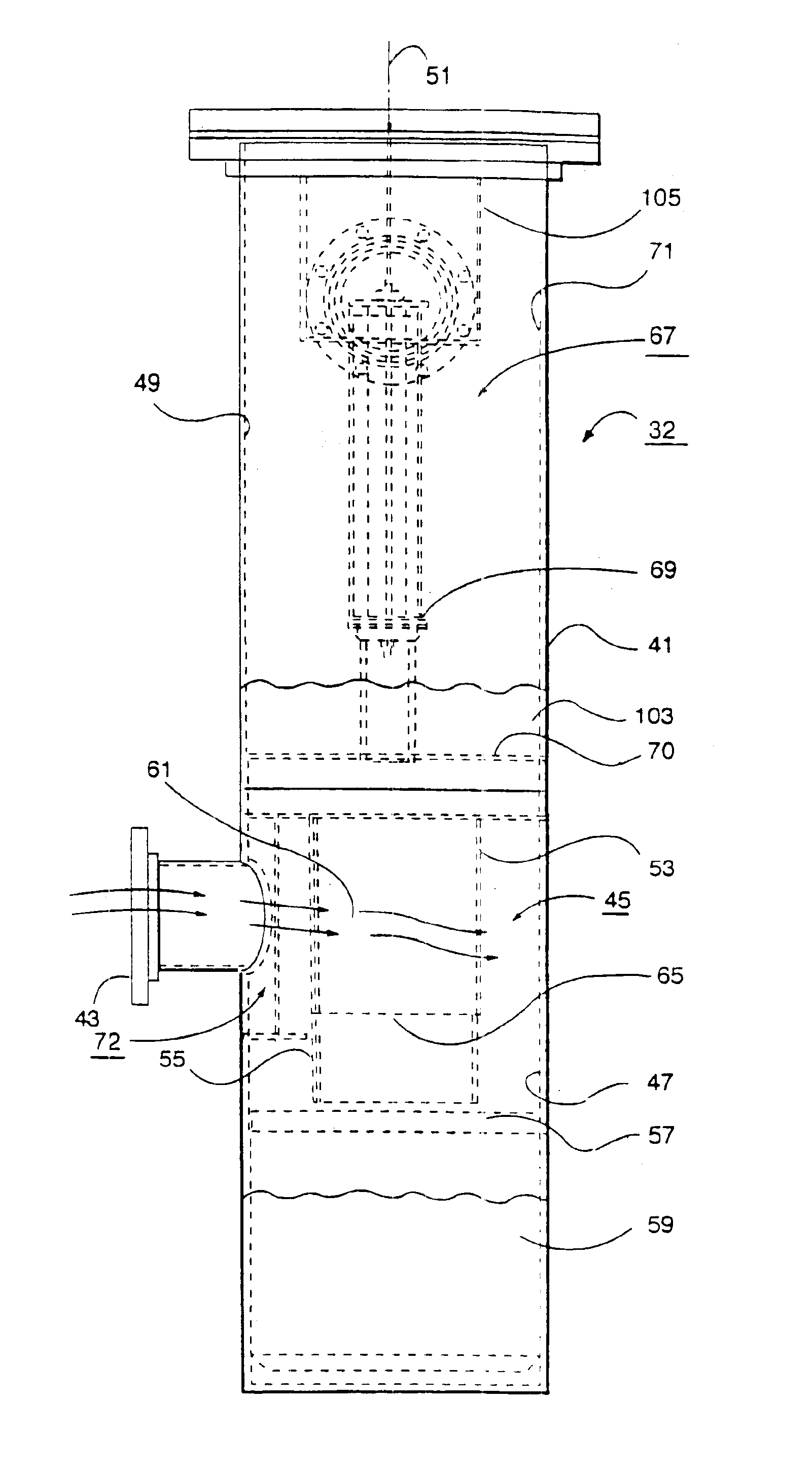
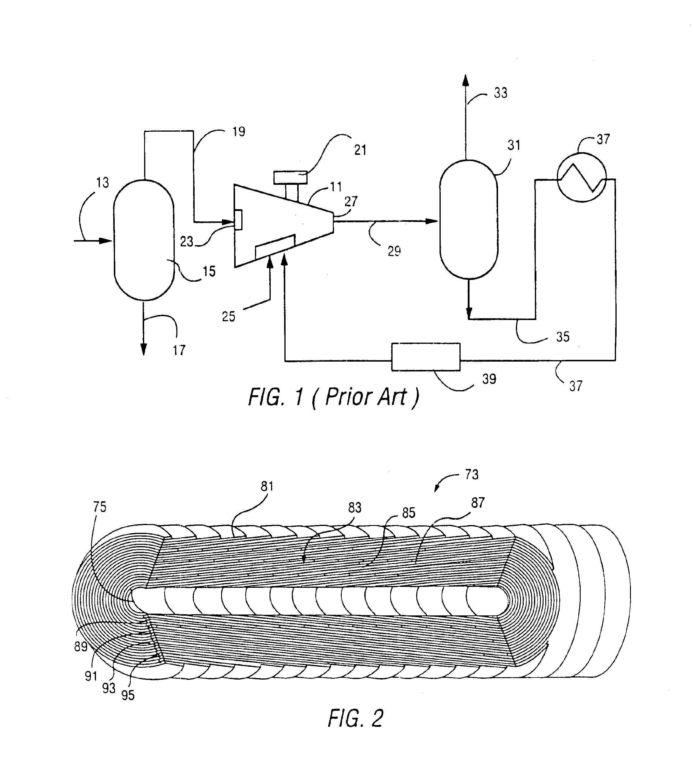
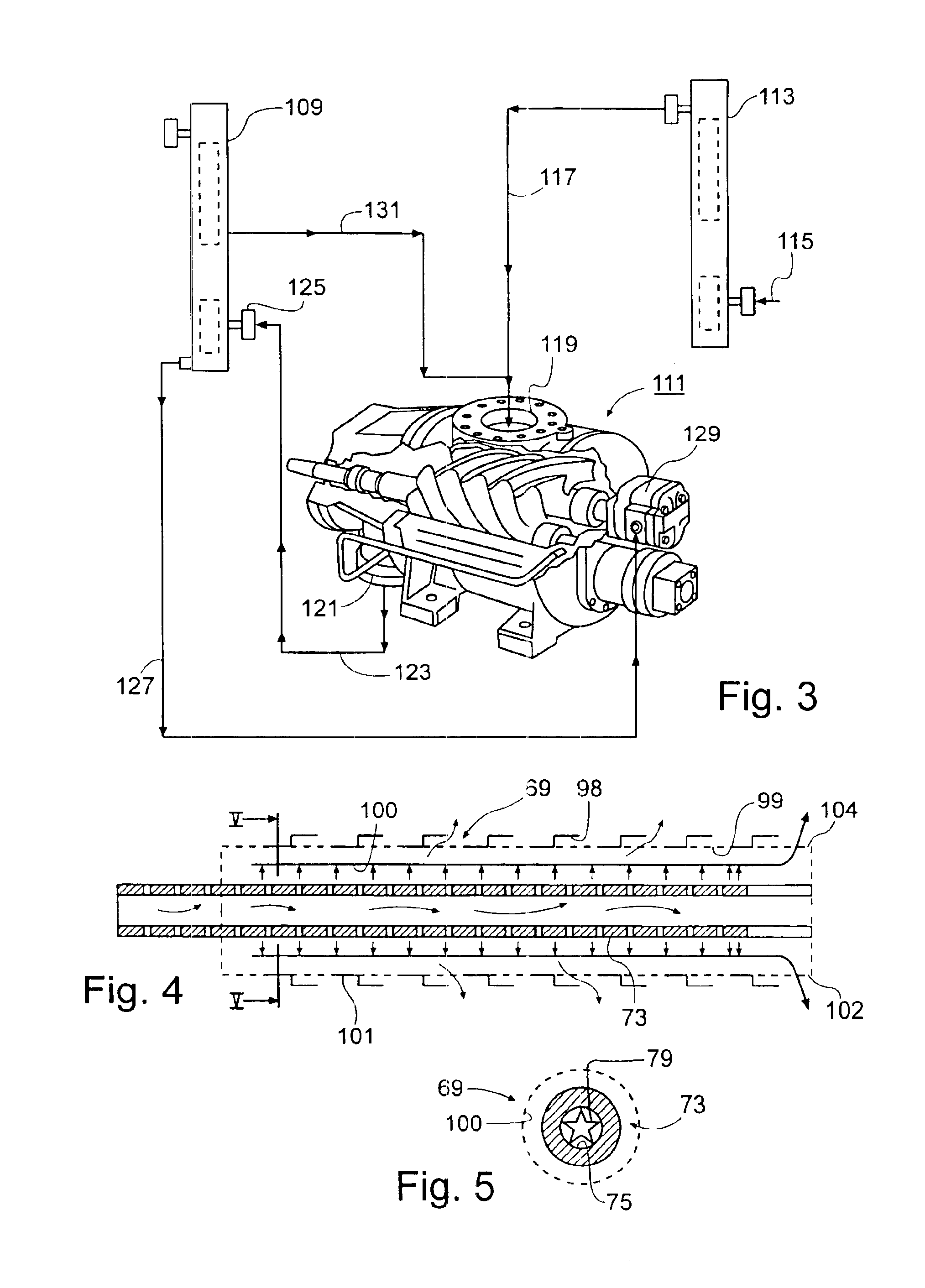
FIG. 1 shows, in simplified schematic fashion, a prior art gas compression process and compressor system utilizing a rotary screw gas compressor 11. The compressor 11 is a conventional oil flooded rotary screw compressor as will be familiar to those skilled in the industry.

A raw gas feed stream 13 from a natural gas well or other source is supplied to a scrubber 15 for separating fluids and entrained solids from the raw gas stream 13. The scrubber 15 may be any conventional two or three phase separator which discharges a liquid stream 17 to a disposal reservoir and an essentially dry, low pressure gas stream 19 to the compressor 11. A portion of the gas stream may also be used to power the prime mover 21 which is used to power the compressor 11. However, a variety of other types of engines or electric motors may also be used to drive the compressor 11.

The compressor 11 receives the low pressure gas through an inlet port 23. A suitable lubricant is supplied to the inside of the casin...


PUM

PropertyMeasurementUnit
diameteraaaaaaaaaa
heightaaaaaaaaaa
centrifugal forceaaaaaaaaaa

Abstract

A filtration vessel is shown for use with a rotary screw compressor which receives a compressed liquid / gas mixture from the compressor. The vessel utilizes a first stage vortex knockout region to remove bulk liquids through a circular motion which imposes centrifugal forces on the gas and liquid mixture. A coalescer region located above the vortex knockout region receives the relatively lighter fluids and separates any remaining entrained liquids from the fluids. The discharge from the filtration unit is an essentially liquid free compressed gas. The liquid discharge, in the case of lube oil can be recirculated to the compressor for another cycle.

Description

BACKGROUND OF THE INVENTION1. Field of the InventionThe present invention relates to a device and method for separating oil in a rotary compressor system and, specifically, to a filtration vessel which acts as a lube oil separation coalescer to eliminate liquid particles from a gas stream utilizing a rotary screw compressor.2. Description of the Prior ArtHelical lobe rotary compressors, commonly referred to as “screw compressors” are becoming more and more popular in the air compressor, refrigeration and natural gas processing industries. These screw type processors utilize rotors or screws to push or compress gas to a higher pressure. Commonly, two cylindrical rotors are mounted on separate shafts inside a hollow, double-barreled casing. The sidewalls of the compressor casing form two parallel, overlapping cylinders which house the rotors in side by side fashion with their shafts generally parallel to the ground. Helically extending lobes and grooves on the exterior surface of the ...

Claims


Application Information

Patent Timeline
Patent Type & Authority Patents(United States)
IPC IPC(8): B01D45/16B01D45/12B01D50/00F04C29/02F04C18/16
CPCB01D45/16B01D50/002F04C29/026Y10S55/17F04C18/16B01D50/20
Inventor BURNS, DAVID J.KROGUE, JOHN A.BORJON, TOMAS I.
Owner PARKER INTANGIBLES LLC
Why Eureka
Try Eureka