Buckling arm robot

a robot and arm technology, applied in the field of buckling arm robots, can solve the problems of limited laser power, power cannot be used, and the particular unfavorable, and achieve the effect of reducing manufacturing costs

Active Publication Date: 2005-02-22
REIS MASCHFAB
View PDF5 Cites 16 Cited by
  • Summary
  • Abstract
  • Description
  • Claims
  • Application Information

AI Technical Summary

Benefits of technology

It is an object of the present invention to provide a buckling arm robot of the aforementioned kind that enables with technically simple mea...

Problems solved by technology

However, this is considered particularly unfavorable, especially in regard to faster working movements, because this laser device significantly contributes to the weight that must be moved together with the third axis.
Accordingly, on the one hand, this causes limitations with regard to the laser power because lasers with greater power cannot be empl...

Method used


Image

  • Buckling arm robot
  • Buckling arm robot
  • Buckling arm robot

Examples


Embodiment Construction

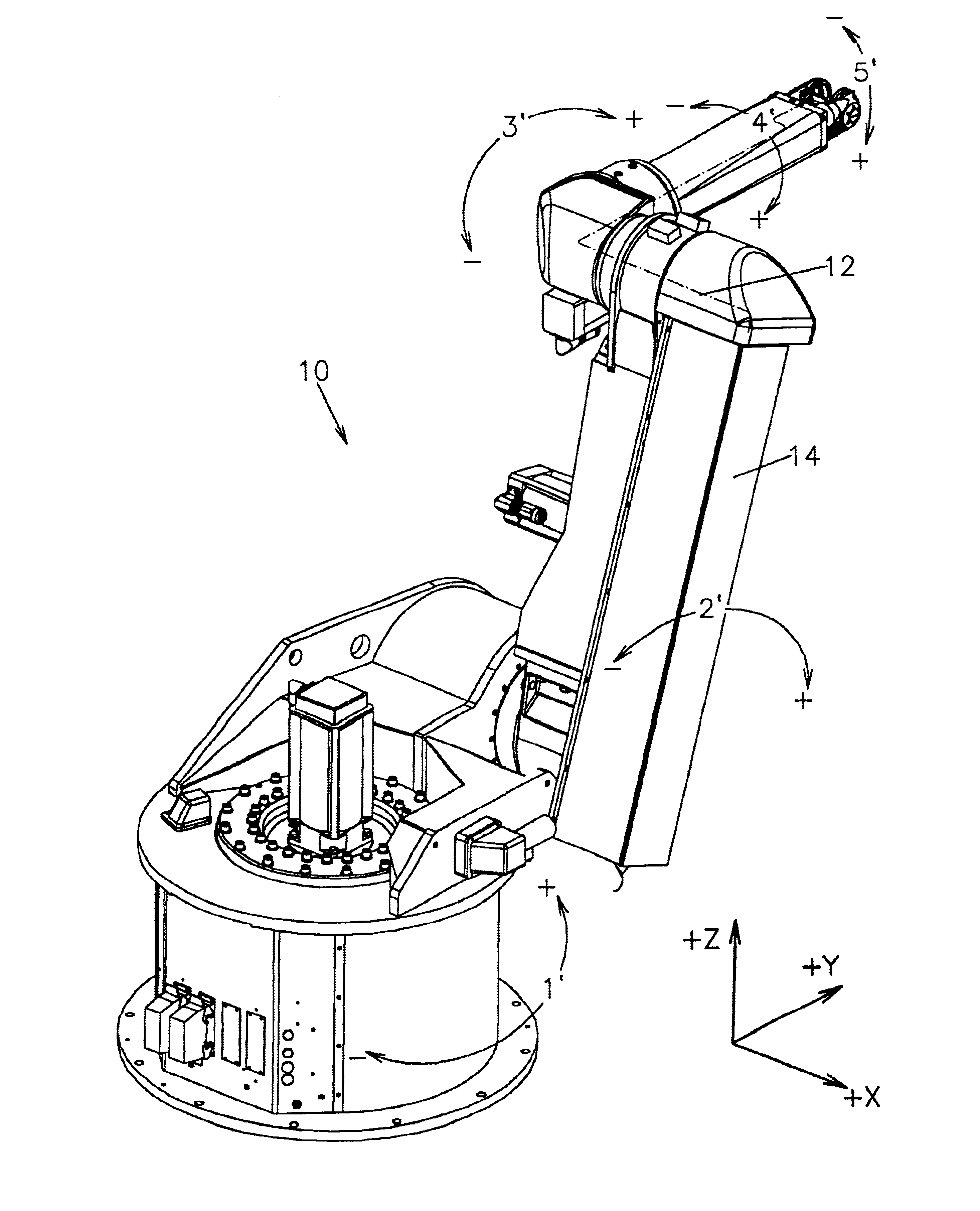
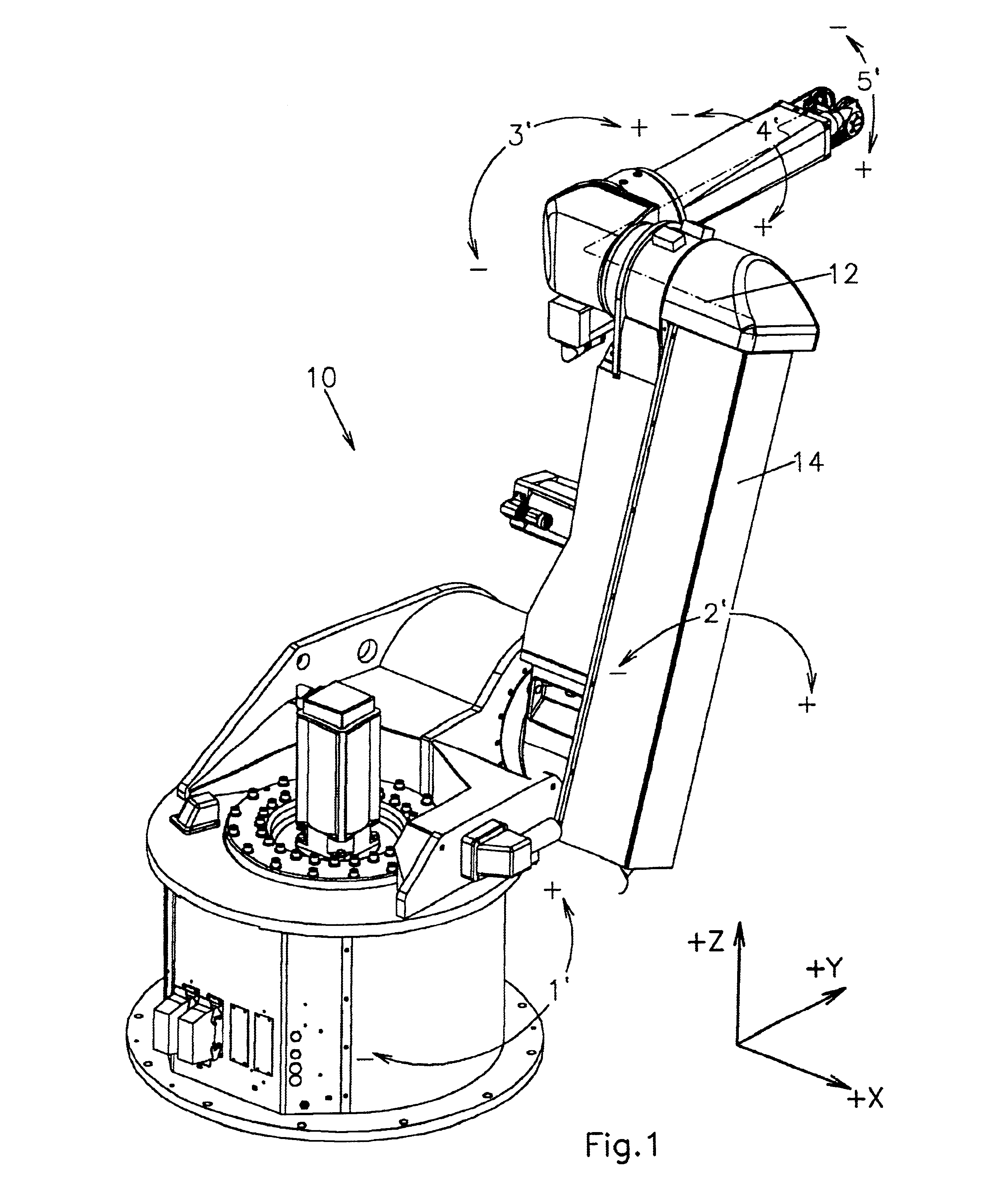
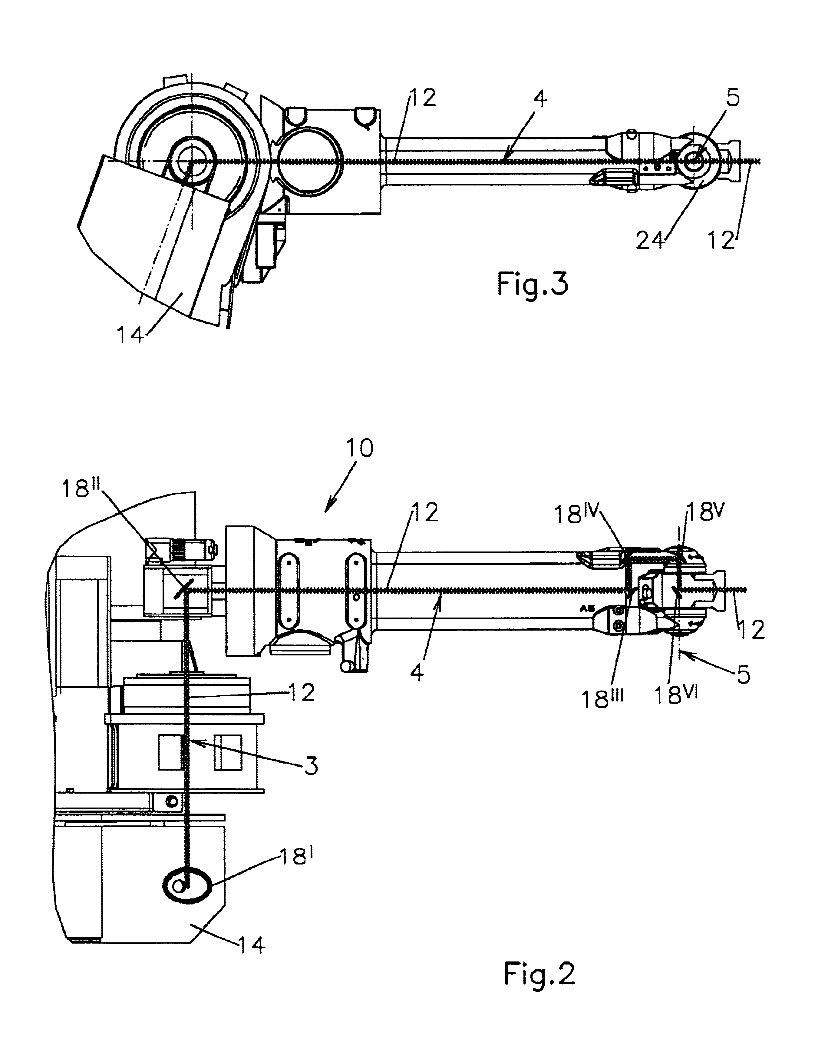
Different embodiments of a buckling arm robot 10, 10′ will be described in connection with FIGS. 1 through 11. If not indicated differently, same elements are identified by same reference numerals. It should be noted that, as is conventional in the field, the term axis does not relate exclusively to the pivot or rotational axes but also to the robot components that are moved about the pivot axes, for example, the robot arms.

The buckling arm robot 10 illustrated in FIG. 1 serves for machining workpieces by means of laser radiation. Such a buckling arm robot is configured in principle as disclosed in German patent document 43 35 367. Such a buckling arm robot 10 is designed such that its individual components can carry out the required movements in all directions of the Cartesian coordinate system within the reach of its axes. This buckling arm robot 10 is provided with first through fifth axes 1, 2, 3, 4, and 5 for three-dimensional machining of workpieces. Each one of these five axe...


PUM

PropertyMeasurementUnit
Lengthaaaaaaaaaa
Angleaaaaaaaaaa
Cell angleaaaaaaaaaa

Abstract

A buckling arm robot for machining workpieces with laser radiation has at least a first axis, a second axis, a third axis, a fourth axis, and a fifth axis. A laser device is arranged in the second axis and configured to emit a laser beam. The laser beam emitted by the laser device is guided within the third, fourth, and fifth axes before striking a workpiece to be machined.

Description

BACKGROUND OF INVENTION1. Field of the InventionThe invention relates to a buckling arm robot for machining workpieces by means of laser radiation, wherein the buckling arm robot has at least first through fifth axes and a laser device.2. Description of the Related ArtA buckling arm robot having the aforementioned features is disclosed, for example, in European patent 0 901 875. This known buckling arm robot is designed such that it can perform the required movements within the reach of its first through fifth axes in all directions of a Cartesian coordinate system. Numbering of these five axes is generally known for buckling arm robots; beginning at the foundation or the ground with the vertically arranged first axis, the axes are numbered in an ascending fashion up to the robot hand. It should be noted that, as is conventional in the field, the term axis does not exclusively denote the pivot or rotational axes but also denotes the robot components that are moved about the axis, fo...

Claims


Application Information

Patent Timeline
IPC IPC(8): B23K26/10B25J19/00
CPCB25J19/0037B23K26/0884
Inventor FISCHER, AXELKROTH, EBERHARD
Owner REIS MASCHFAB
Why Eureka
Try Eureka