Integrated spiral and top-loaded monopole antenna

a spiral and top-loaded technology, applied in the field of low-profile antennas, can solve the problems of narrow frequency bandwidth, low power available from satellites, and expensive and aesthetically disassuring the appearance of several antennas on a vehicle, so as to reduce the reduce the required length of the monopole antenna, and increase the frequency. the effect of bandwidth

Inactive Publication Date: 2005-02-22
GM GLOBAL TECH OPERATIONS LLC
View PDF4 Cites 28 Cited by
  • Summary
  • Abstract
  • Description
  • Claims
  • Application Information

AI Technical Summary

Benefits of technology

In yet other features, the first antenna is fed by a first coaxial cable having an inner conductor and an outer conductor and the monopole antenna is fed by a second coaxial cable having an inner conductor and an outer conductor. An enclosure is located below the hollow tube that contains an additional circuit for the antenna. The ground plane is a metal surface of a vehicle. The disk reduces a length of the monopole antenna required for a desired frequency of the monopole antenna to be at a fundamental resonance level. The disk increases a bandwidth of frequencies of the fundamental resonance level for the top-loaded monopole antenna. The support structure is a housing including a dielectric material. The dielectric material includes Lexan polycarbonate and reduces a required length of the monopole antenna. The first antenna and the monopole antenna operate in a Direct Broadcast Satellite (DBS) radio system. The material is a low loss dielectric.

Problems solved by technology

Providing several antennas on a vehicle is costly and aesthetically displeasing.
This is due to the low power available from satellites.
This requires the antenna to operate at a higher order resonance, which results in a narrow bandwidth of frequencies.
However, these antennas are large and not aerodynamic or aesthetically pleasing when mounted on the exterior of the vehicle.

Method used


Image

  • Integrated spiral and top-loaded monopole antenna
  • Integrated spiral and top-loaded monopole antenna
  • Integrated spiral and top-loaded monopole antenna

Examples


Embodiment Construction

The following description of the preferred embodiment(s) is merely exemplary in nature and is in no way intended to limit the invention, its application, or uses. For purposes of clarity, the same reference numbers will be used in the drawings to identify similar elements.

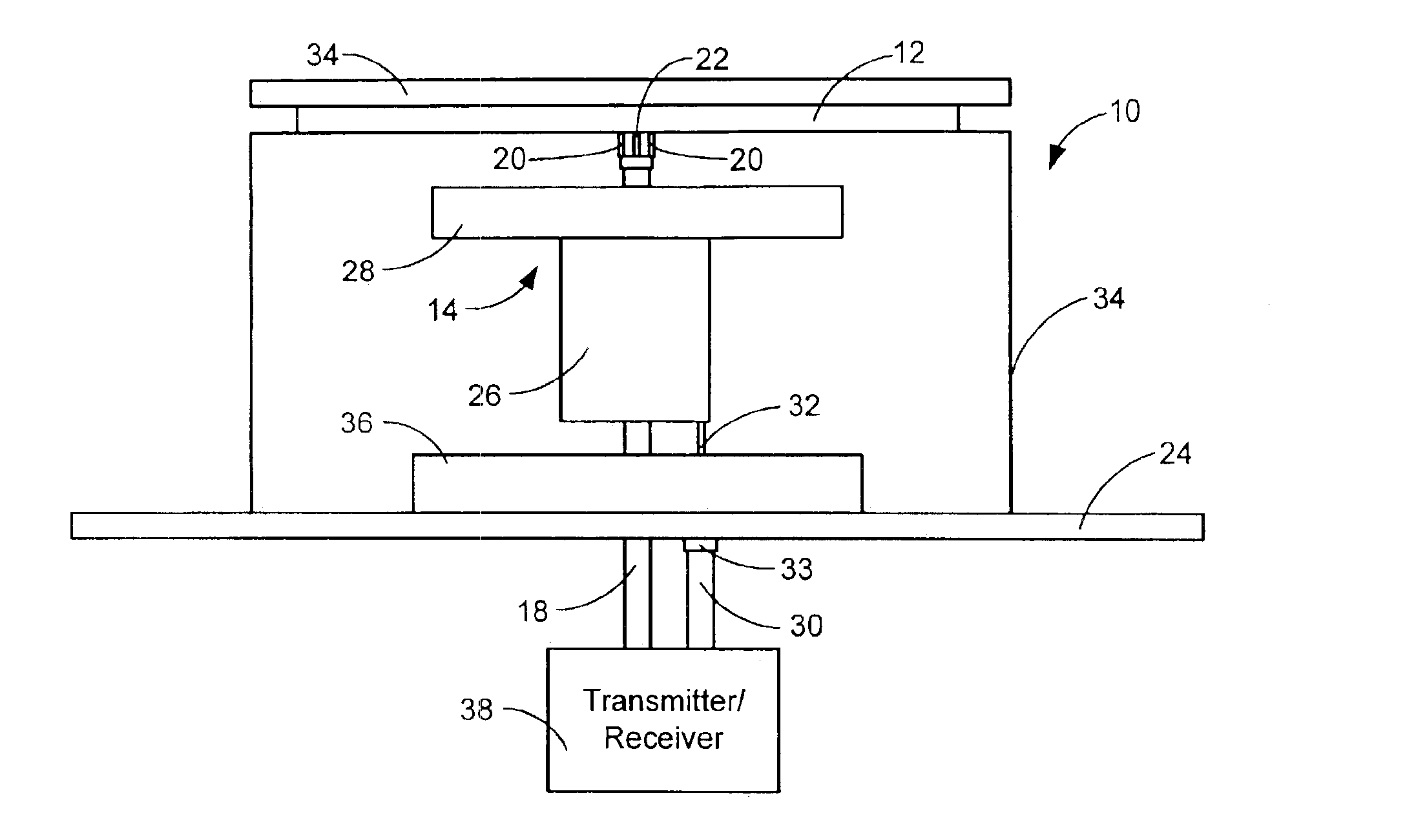
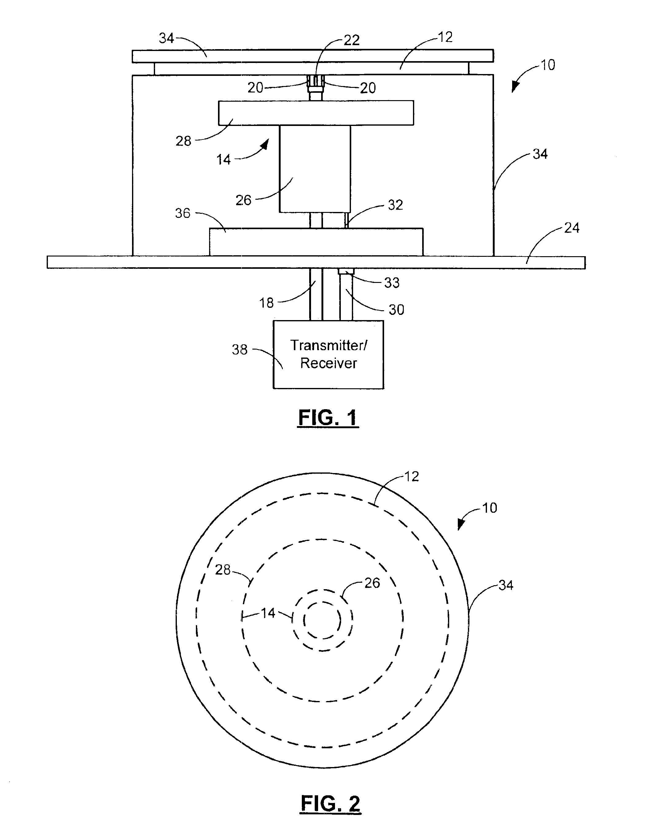
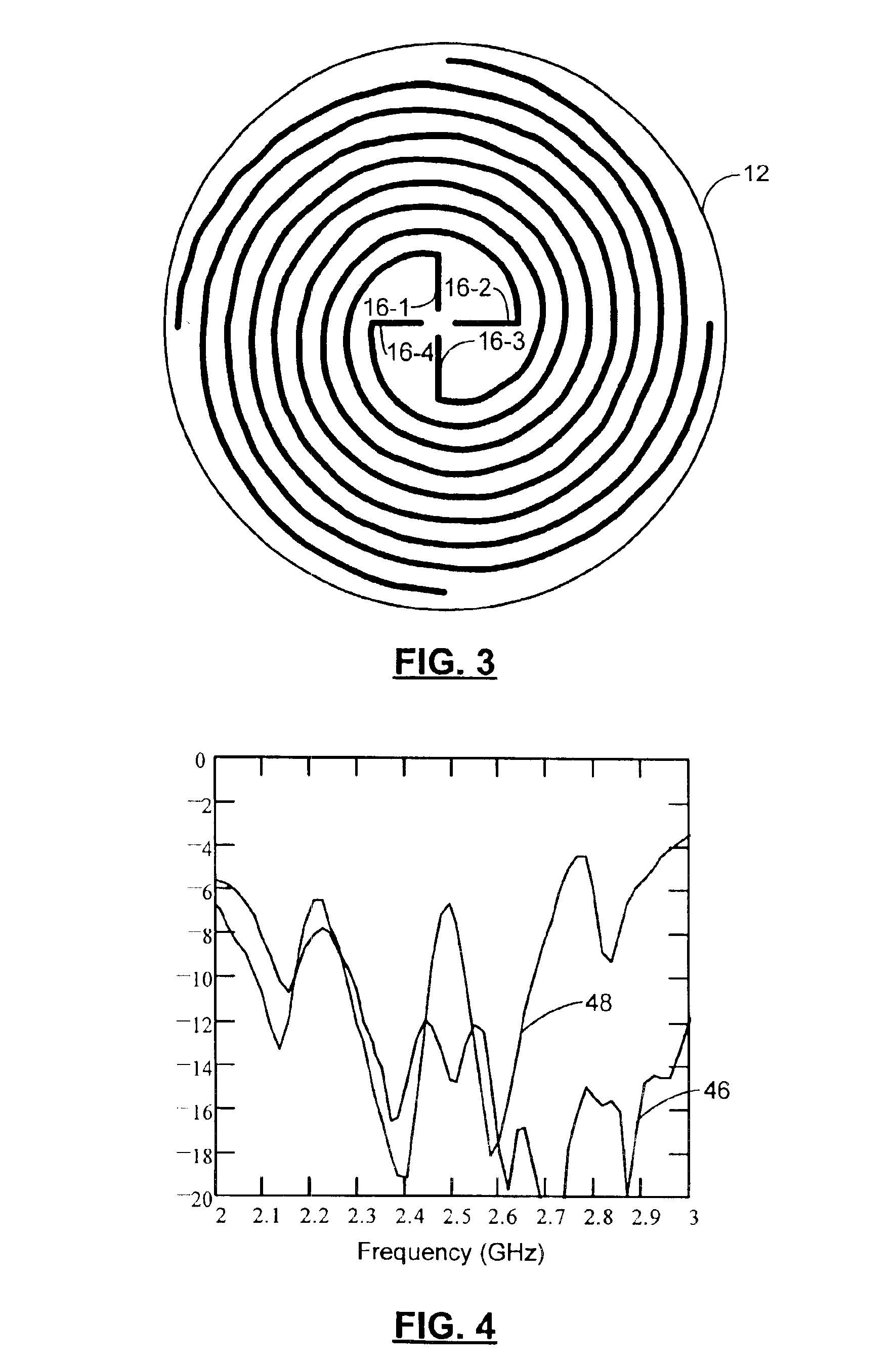
Referring now to FIGS. 1-3, an antenna 10 includes a spiral antenna 12 and a top-loaded monopole antenna 14 that are integrated for independent or simultaneous operation. In FIG. 3, an exemplary embodiment of the spiral antenna 12 is shown to include a spiral structure with independent arms 16-1, 16-2, 16-3, and 16-4 that spiral and converge in a middle of the spiral antenna 12.

The spiral antenna 12 is fed by a first cable 18 with a first conductor 20 and a second conductor 22. The first conductor 20 is connected to a first pair of nonadjacent arms (16-1 and 16-3) or (16-2 and 16-4) of the spiral antenna 12. The second conductor 22 is connected to a second pair of nonadjacent arms (16-2 and 16-4) or (16-1 and 16-3)...


PUM


Abstract

A low-profile antenna provides dual simultaneous operation. A first antenna has a circular polarization radiation pattern. A monopole antenna includes a hollow tube and is top-loaded by locating a disk on top of the hollow tube. A support structure positions the monopole antenna between the first antenna and a ground plane. The first antenna is a four arm spiral antenna. The four arm spiral antenna and monopole antenna are each fed by a cable with a first conductor and a second conductor. The radiation pattern of the four arm spiral antenna is maximum at forty-five degrees above the horizon and is null toward the horizon. The cable excites the monopole antenna with respect to the ground plane to transmit / receive vertical polarized signals. The radiation pattern of the monopole antenna is maximum towards the horizon. The first antenna and the monopole antenna operate simultaneously.

Description

FIELD OF THE INVENTIONThe present invention relates to low-profile antennas, and more particularly to multiple function low-profile antennas.BACKGROUND OF THE INVENTIONLow-profile antennas are typically used in vehicles. The low-profile antennas are commonly mounted on an exterior of the vehicle. For aesthetic reasons, the low-profile antennas are preferably small in size. Various vehicle systems may require an antenna such as cellular phones, satellite radio, terrestrial radio, and / or global positioning systems (GPS). Providing several antennas on a vehicle is costly and aesthetically displeasing.Geosynchronous satellite communication systems require the transmission and / or reception of circular polarized signals. Terrestrial communication systems require the transmission and / or reception of vertical polarized signals. Often these signals need to be communicated simultaneously.A Direct Broadcast Satellite (DBS) radio system broadcasts radio frequency (RF) signals from a satellite t...

Claims


Application Information

Patent Timeline
Patent Type & Authority Patents(United States)
IPC IPC(8): H01Q21/24H01Q5/00H01Q11/10H01Q9/04H01Q9/27H01Q1/32H01Q11/00
CPCH01Q1/3275H01Q9/27H01Q21/30H01Q21/24H01Q11/105
Inventor COLBURN, JOSEPH S.LYNCH, JONATHAN J.
Owner GM GLOBAL TECH OPERATIONS LLC
Why Eureka
Try Eureka