Integrated bidirectional Recording head micropositioner for magnetic storage devices

a magnetic storage device and recording head technology, applied in the direction of recording information storage, maintaining head carrier alignment, instruments, etc., can solve the problem that the conventional gimble assembly does not permit the recording head to move in the z direction, and achieve the effect of fast settle on a selected track, high density storage, and reliable stay on track

Inactive Publication Date: 2005-02-22
MEYER DALLAS W
View PDF28 Cites 47 Cited by
  • Summary
  • Abstract
  • Description
  • Claims
  • Application Information

AI Technical Summary

Benefits of technology

A micropositioner integrated into the slider body controls the position and movement of the transducer body with respect to the slider body. In effect, the use of a micropositioner integrated into the slider body results in the small scale motion of the transducer being controlled at the recording head rather than at the actuator that controls the rotational motion of the entire head gimble assembly. Controlling the small scale motion in this manner provides several distinct and substantial advantages compared to conventional disk drives. For instance, the micropositioner in the recording head enables the transducer to be reliably positioned with respect to the tracks on the magnetic storage medium, thereby overcoming many of the problems associated with track following experienced in the industry. Because the resonant frequencies of the transducer body that is moved by the micropositioner can be as high as 30 kHz or higher, the transducers of invention can settle on a selected track much more quickly and reliably than those used in conventional disk drives. The ability to quickly settle onto a selected track and reliably stay on track represents a significant improvement over conventional devices, and permits the recording heads of the invention to be advantageously used with current storage media as well as higher density storage media that will be developed in the future.
The two directions of motion generated by the micropositioners of the invention include the x direction, which is defined to be parallel to the surface of the recording medium as well as perpendicular to the tracks, and the z direction, which is defined to be perpendicular to the surface of the recording medium. Control at the recording head of the z position of the transducer greatly enhances the ability to control the fly height of the transducer during operation. In contrast, conventional head gimble assemblies do not permit the recording head to be moved in the z direction. The ability to control the position of the transducer in the z direction is useful in combination with conventional magnetic storage media, as well as higher density storage media that will be developed in the future, in which the fly height will be even more critical.
Control of the transducer in the z direction enables a number of novel methods that enhance the use, initialization, and fabrication of disk drives and recording heads. For instance, the control of the transducer in the z direction permits the transducer to be displaced over asperities in the surface of a magnetic storage medium, thereby reducing media contact by the transducer and prolonging the life thereof. In addition, the z position of the transducer can be adjusted in response to temperature and pressure measurements, so as to maintain a desired fly height in different environmental conditions. Moreover, the micropositioners of the invention can be used to achieve desired dimensional tolerances of the recording heads themselves during the fabrication process.

Problems solved by technology

In contrast, conventional head gimble assemblies do not permit the recording head to be moved in the z direction.

Method used


Image

  • Integrated bidirectional Recording head micropositioner for magnetic storage devices
  • Integrated bidirectional Recording head micropositioner for magnetic storage devices
  • Integrated bidirectional Recording head micropositioner for magnetic storage devices

Examples


Embodiment Construction

The present invention relates to recording heads having an integrated micropositioner for controlling the motion and position of transducer elements with respect to magnetic storage media. Micropositioners can be used to control the position of the transducer elements in either of two directions, which permits recording heads to be reliably used with existing recording media as well as with higher density recording media that will be developed in the future.

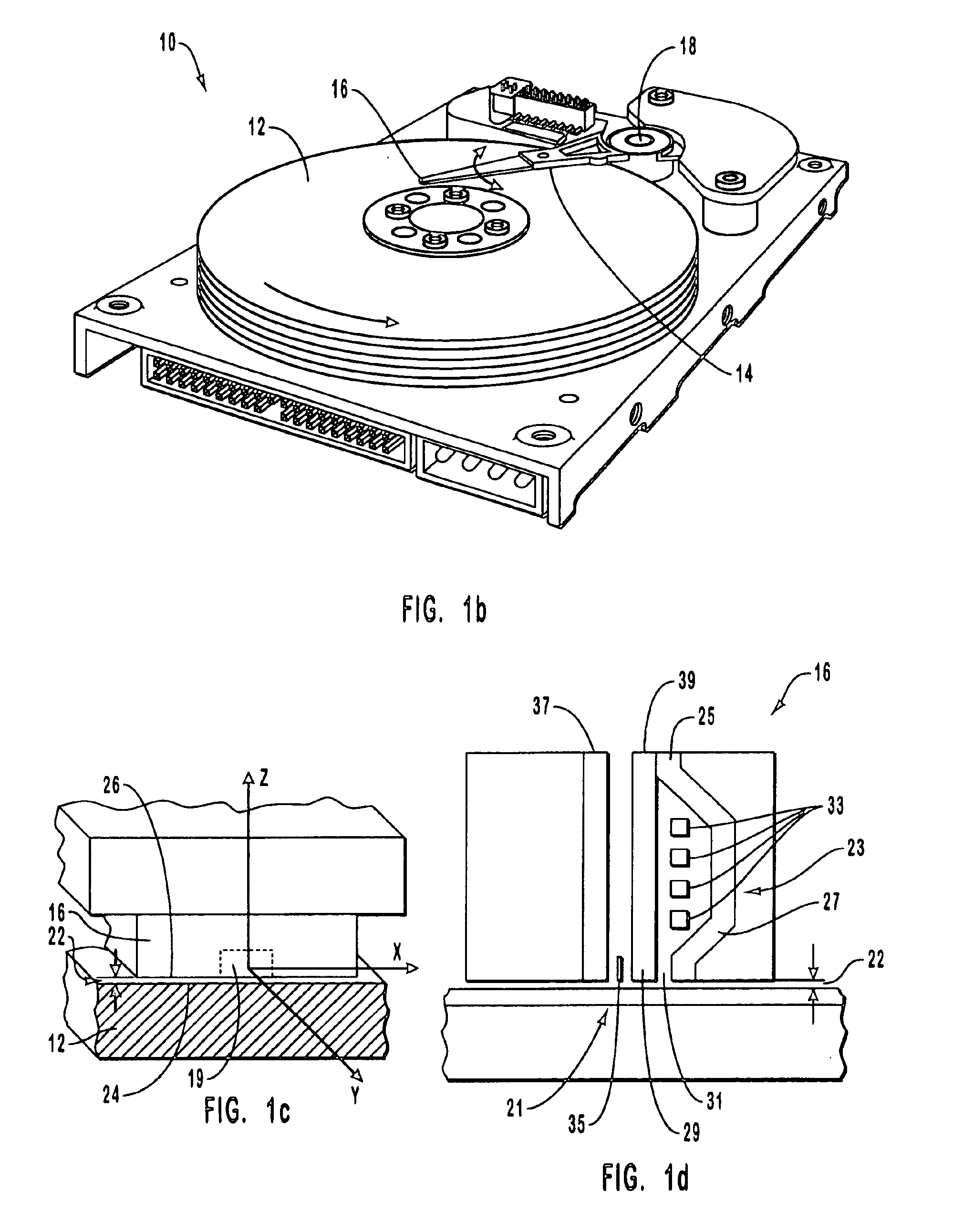
While FIGS. 1b and 1c illustrate conventional disk drives, these figures set forth a convention regarding the frame of reference that is useful in describing the operation of the recording heads of the invention. As shown in FIG. 1b, rotating magnetic storage medium 12 rotates counterclockwise, such that elements on the storage medium that encode individual bits of data travel under recording head 16 in a direction that is substantially parallel to the longitudinal axis of the arm of the head / gimble assembly 14. In other words, a...


PUM

PropertyMeasurementUnit
resonant frequencyaaaaaaaaaa
lengthaaaaaaaaaa
lengthaaaaaaaaaa

Abstract

Transducer elements of recording heads for magnetic storage media are moved independently in either of two directions with respect to the slider of the recording head. The motion is controlled using a micropositioner having magnetic coils integrated into the recording head. The transducer moves in the x direction between data tracks and in the z direction perpendicular to the surface of the magnetic storage medium. The micropositioners are used for small-scale positioning of the transducers over data tracks and to adjust fly heights. Because of the high minimum resonant frequencies and the low mass of the transducers, the micropositioners also improve settling times associated with track following. The micropositioners can be used during fabrication for dimensional control of recording head components. The motion of the transducers in the z direction enables the recording heads to be used reliably in the presence of asperities and changing ambient pressures and temperatures.

Description

2. The Field of the InventionThe present invention relates to data storage on rotating magnetic storage devices. More specifically, the present invention relates to recording heads used with rotating magnetic storage devices in which a micropositioner reliably and rapidly controls the motion and position of a transducer element.3. The Relevant TechnologyDuring recent years, there has been a steady improvement in the volume of data that can be stored on magnetic storage media, such as hard disks drives used in computers. Today, a single 3.5 inch magnetic storage disk can store twenty gigabytes or more of data. At the same time, storage capacity per unit cost has fallen dramatically, which has enabled individual users and enterprises to radically change the way in which data is recorded and stored. Indeed, the ability to store large volumes of data inexpensively has been a driving factor in the information technology revolution during recent decades.Conventional storage media include ...

Claims


Application Information

Patent Timeline
Patent Type & Authority Patents(United States)
IPC IPC(8): G11B5/56G11B5/127G11B5/17G11B5/60
CPCG11B5/17G11B5/1274
Inventor MEYER, DALLAS W.
Owner MEYER DALLAS W
Why Eureka
Try Eureka