Capacitor sheet

a technology of capacitors and sheets, applied in the field of capacitor sheets, can solve problems such as lack of flexibility

Active Publication Date: 2005-02-22
FUJITSU LTD
View PDF11 Cites 12 Cited by
  • Summary
  • Abstract
  • Description
  • Claims
  • Application Information

AI Technical Summary

Problems solved by technology

In the above-mentioned patent document 1, there is a problem that a power supply point associated with the BGA package is determined, and an electrode location providing a capacitance is fixed.
Accordingly, in order to accommodate to the case where a plurality of power supplies exist (when e.g. 3.3 V, 1.8 V, and the like are used) in the BGA, a plurality of dielectric layers and a plurality of power supply layers sandwiching the dielectric layers have to be formed, and custom products have to be provided according to kinds of power supplies, which leads to a problem of lacking in flexibility.

Method used


Image

  • Capacitor sheet
  • Capacitor sheet
  • Capacitor sheet

Examples


Embodiment Construction

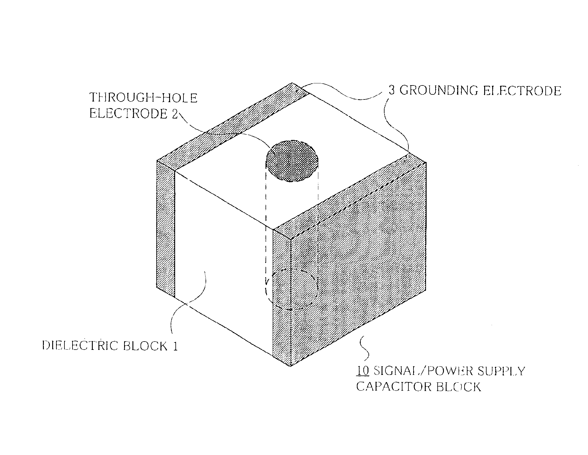
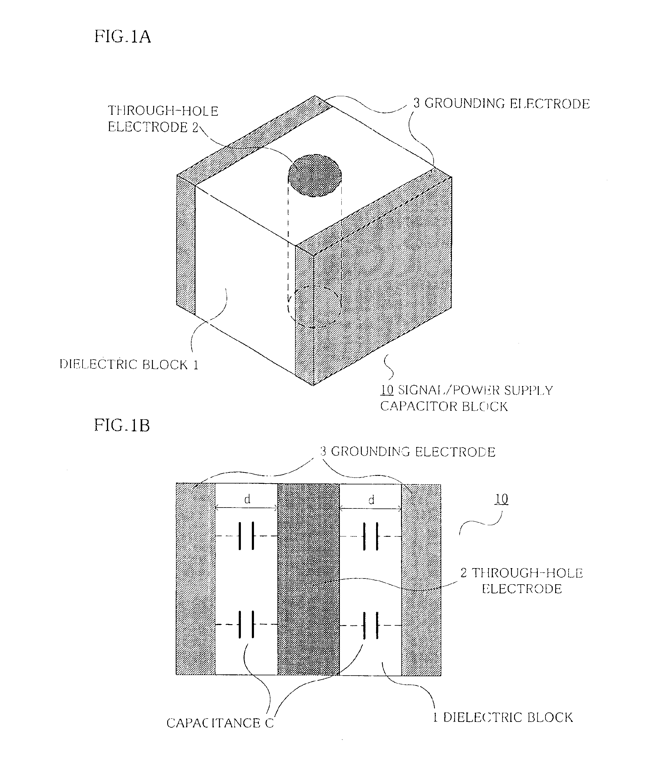
FIGS. 1A and 1B show an embodiment [1] of a signal / power supply capacitor block used for a capacitor sheet according to the present invention. FIG. 1A shows an external view, and FIG. 1B shows an equivalent circuit view.

In FIG. 1A, a signal / power supply capacitor block 10 has a through-hole electrode 2 in a near center of a dielectric block 1 of a cube or a rectangular parallelepiped. On two sides of the dielectric block 1, to which the through-hole electrode 2 is not exposed, grounding electrodes 3 are provided or plated. It is supposed that the through-hole electrode 2 is embedded in the dielectric block 1 by the Pb-plating, or the like.

In the capacitor block 10, as shown in an equivalent circuit view of FIG. 1B, a capacitance C is formed between the through-hole electrode 2 and the grounding electrodes 3. The capacitance C is formed in upward and downward direction, i.e. a vertical direction of the figure.

The capacitance in this case can be schematically obtained based on the fol...


PUM


Abstract

A capacitor sheet comprises a plurality of first capacitor blocks connecting signal/power supply electrodes of two circuit boards with through-hole electrodes, and having grounding electrodes sandwiching dielectrics around the through-hole electrodes, and a plurality of second capacitor blocks connecting the grounding electrodes in two circuit boards with the through-hole electrodes, and having the grounding electrodes sandwiching the dielectrics around the through-hole electrodes, wherein the through-hole electrodes and the grounding electrodes are connected with pattern wirings. The capacitor blocks are arranged so that the grounding electrodes in the first capacitor blocks are electrically connected to the grounding electrodes of the second capacitor blocks to be combined to a single piece.

Description

BACKGROUND OF THE INVENTION1. Field of the InventionThe present invention relates to a capacitor sheet, and in particular to a capacitor sheet for removing noises of an LSI or the like on a circuit substrate in a general electronic apparatus such as a communication apparatus or equipment.2. Description of the Related ArtIn order to suppress noises emitted from a circuit substrate and to stabilize a signal waveform, an electronic part such as an IC or an LSI mounted on the circuit substrate mounts a capacitor in the vicinity between a power supply pin and a ground of the IC, the LSI, or the like, for the power supply.FIGS. 12A-12C show such prior art capacitor mounting technologies.Firstly in the prior art example shown in FIG. 12A, in order to realize a high-density mounting, an electronic part such as the IC or the LSI uses a ball grid array (hereinafter, abbreviated as BGA) 21 for the circuit substrate. On the BGA 21, a grounding bump (electrode) 211 and a signal / power supply bump...

Claims


Application Information

Patent Timeline
Patent Type & Authority Patents(United States)
IPC IPC(8): H01G2/00H01G2/06H01G4/35H01G4/38H01G4/228H01G4/252H01L23/12H01L23/32H01L21/60H01L23/498H01L23/50H05K1/02H05K1/16
CPCH01G4/35H01L23/50H05K1/0231H01L23/49827H05K2201/10734H01L24/81H01L2224/16H01L2224/81801H01L2224/82H01L2224/85H01L2224/86H01L2924/01078H01L2924/15311H01L2924/19103H01L2924/19105H01L2924/19106H01L2924/3011H05K1/0219H05K1/162H05K2201/10378H01L2924/14H01L2924/00
Inventor KANASAKI, KATSUMIIMABAYASHI, HIROFUMIMIYAZAKI, TAKEHIDEOKADA, AKIRA
Owner FUJITSU LTD
Why Eureka
Try Eureka