Tool head of a trimmer

a technology of tool head and trimmer, which is applied in the field of tool head of brush cutter or trimmer, can solve problems such as the function of the trimmer being affected, and achieve the effects of improving the handling of the trimmer, and reducing the cost of the trimmer

Inactive Publication Date: 2005-03-01
ANDREAS STIHL AG & CO KG
View PDF5 Cites 2 Cited by
  • Summary
  • Abstract
  • Description
  • Claims
  • Application Information

AI Technical Summary

Benefits of technology

Material that has been cut off and accumulates on the hub portion is thus carried along with the rotational movement of the hub portion until it encounters the stripping edge. At this location, the stripping edge leads to a reliable removal of the cut material from the hub portion, and prevents a winding-on of longer cut material that builds up over a number of rotations. Due to the removal or stripping of the cut material via the cutting edge, lower centrifugal forces are also adequate for releasing cut material. The tool head and the hub portion can be of compact construction with small diameters, thereby improving the handling of the trimmer. The reliable removal even of wet cut material that tends to stick increases the operational reliability and hence the productivity of the trimmer.
Pursuant to one advantageous further development, the stripping edge, relative to the contour of the hub portion, has a radially inwardly disposed edge portion, so that the stripping edge extends from this radially inwardly disposed edge portion to a radially outwardly disposed edge portion. Consequently, a flat side that faces the tool head, and that is part of a hub portion that projects beyond the tool head, can also be reliably kept free of accumulations of cut material. To improve the stripping effect, the stripping edge has a course that rotates along with the tool shaft and extends at an angle from the inside to the outside. The inclined course leads to a peeling effect with little expenditure of energy, and enhances the transporting away of accumulations in a radially outward direction.
Where the stripping edge is embodied as a sharpened cutting edge, in addition to a scraping or peeling off of accumulations, a reduction in size and hence a simplified transporting away of particles that have been deposited on the hub portion is also achieved. A stripping surface that is associated with the stripping edge and is disposed transverse to the direction of movement of the hub portion enhances the outward transporting away of loosened accumulations in that the transversely-disposed stripping surface conducts the removed material laminarly outwardly and avoids a raising of the deposited cut material beyond the stripping edge in a direction toward the inner region of the tool head. In this connection, the stripping surface is disposed either approximately parallel to the axial direction of the tool shaft, or is disposed at a slightly inclined angle relative thereto. A slight incline of the stripping surface leads to a more pronounced defining of the stripping edge or the sharpened cutting edge, and facilitates the removal of deposits or accumulations in the axial direction. The last-mentioned effect can be enhanced by a concave curvature of the stripping surface, which leads to a peeling away of the accumulations with a high effectiveness at a low energy requirement, thereby avoiding a braking effect upon the tool shaft.
Pursuant to an expedient further development, the stripping edge is formed by an arresting flange that projects radially from the tool head and serves for accommodating arresting means for the tool shaft. For example, arresting means can be guided through a bore in the arresting flange and can be introduced into an engagement opening in the hub portion. This blocks the rotatability of the tool shaft. It is then readily possible to exchange a cutting tool on the tool shaft. In this connection, the arresting flange fulfills a dual function of arresting the tool shaft and as a stripping device. While avoiding corresponding structural and manufacturing expenses, no additional devices are required for forming an appropriate stripping edge. The engagement opening on the hub portion for the arresting means is advantageously embodied so as to be open outwardly in the radial direction. This prevents cut-off material from accumulating in the engagement opening. Particles that have been cut off can readily be flung outwardly out of this region due to the effective centrifugal force. The hub portion, which interacts with the stripping edge, is advantageously a pressure plate or a cutting tool that is to be disposed thereagainst. The flat configuration of the pressure plate, with a relatively large diameter, leads to a good flinging-away effect. Due to its arrangement directly between the gear mechanism housing and the rotatable tool, and in conjunction with the stripping edge, the entire hub region between the rotatable cutting tool and the gear mechanism housing is reliably kept free from deposits of dirt.

Problems solved by technology

In particular, wet material that has been cut off, and which is therefore sticky, can accumulate in this region without it being possible for the centrifugal forces to adequately fling this material off.
Longer material such as grass or the like can be wound onto the hub region and can lead to impairment of the function of the trimmer.
Especially with embodiments where a pressure plate for the cutting tool that is to be disposed thereagainst projects radially beyond the outer contour of the tool head, such an undesirable winding of cut-off material onto the hub portion is reinforced.

Method used


Image

  • Tool head of a trimmer
  • Tool head of a trimmer
  • Tool head of a trimmer

Examples


Embodiment Construction

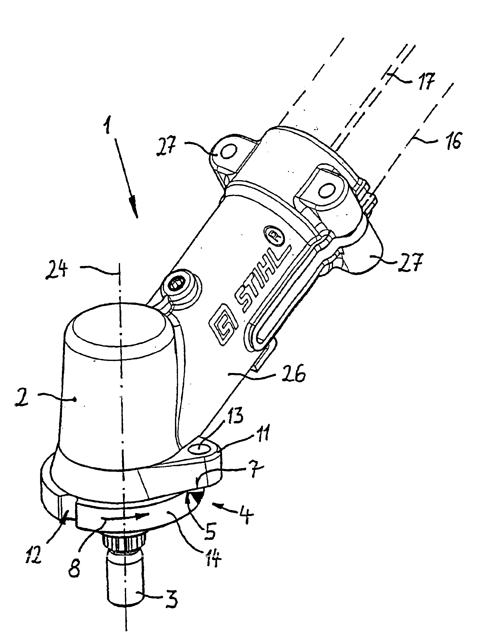
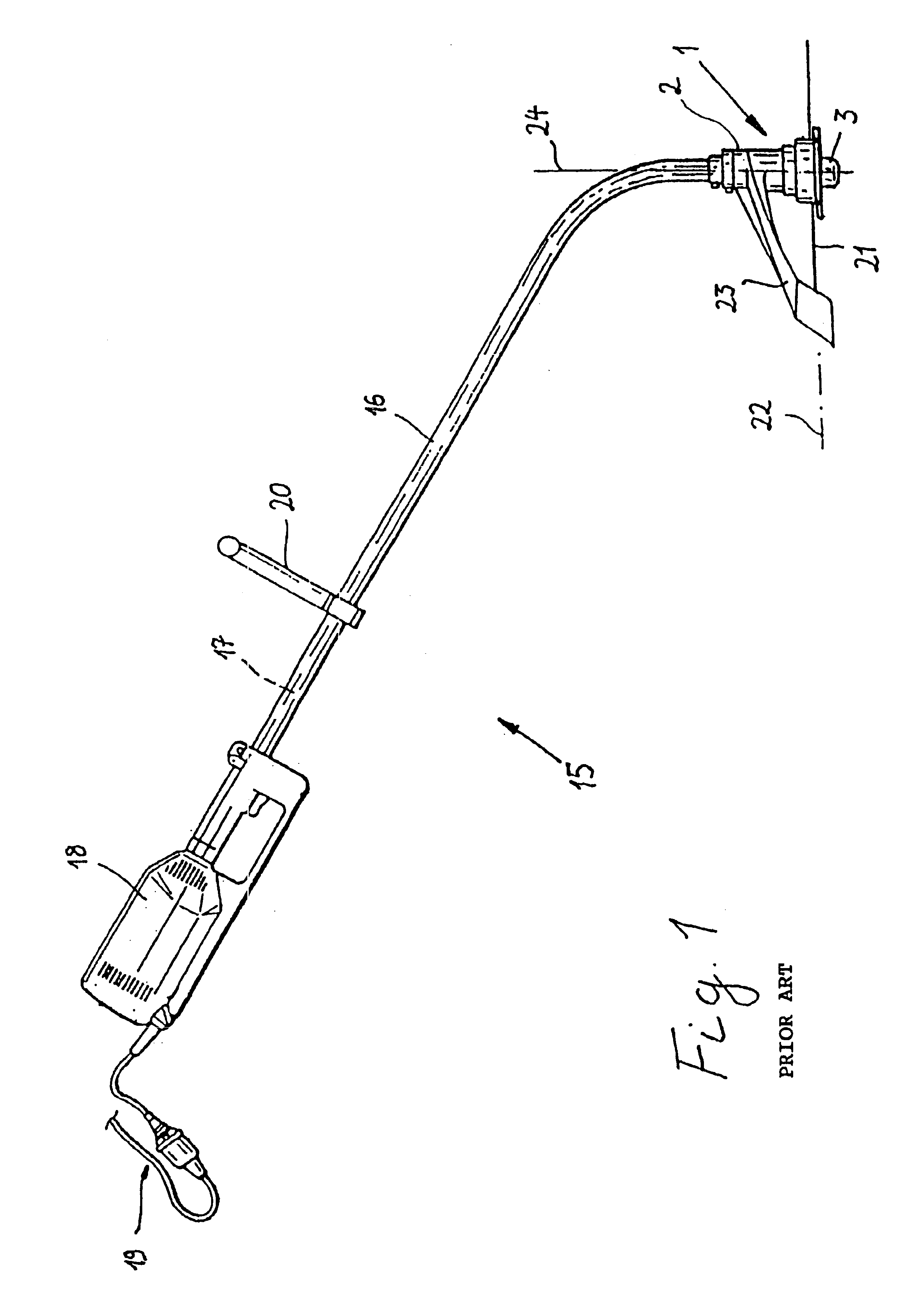
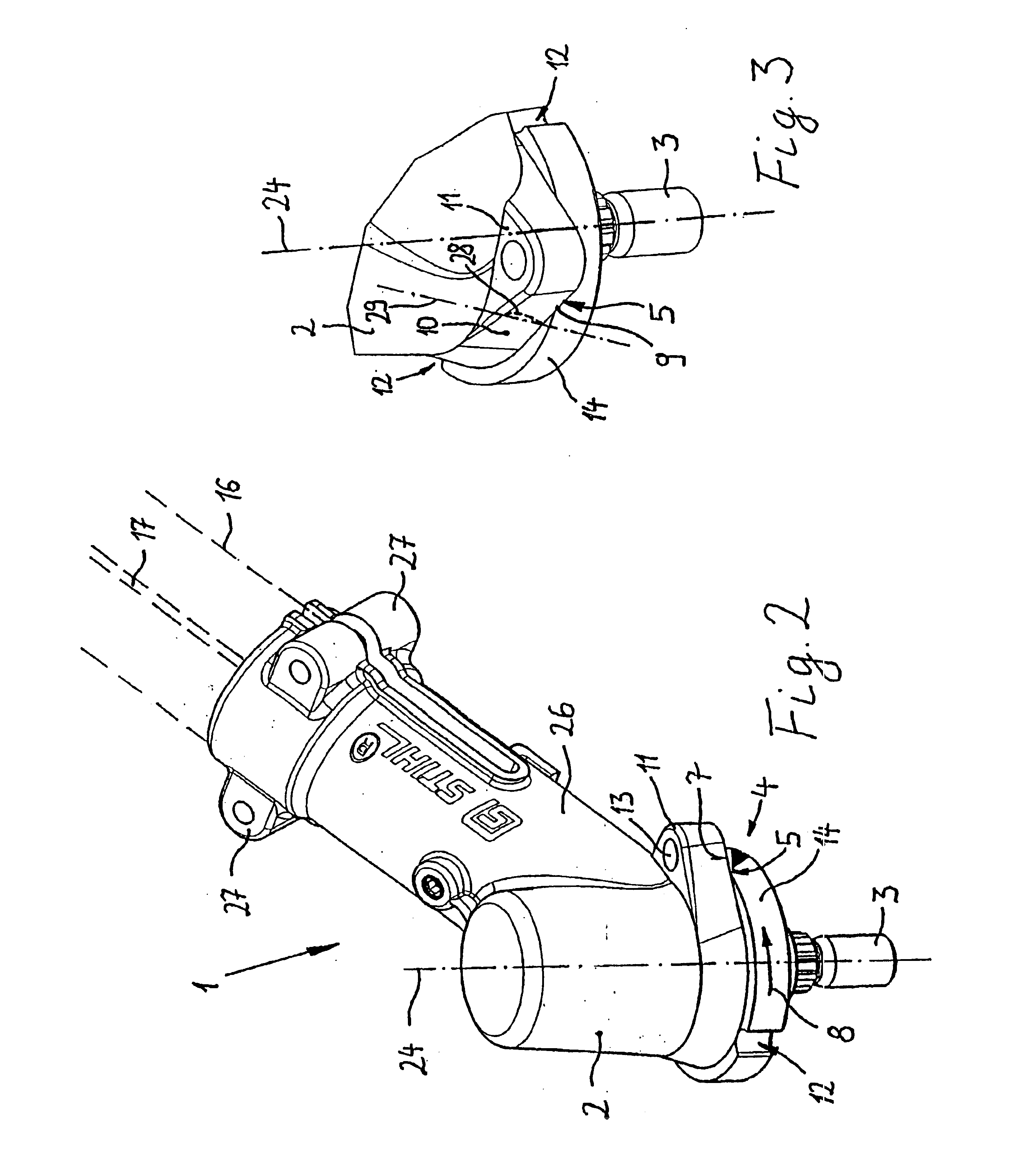
Referring now to the drawings in detail, FIG. 1, in a side view and in general, shows a brush cutter or trimmer 15 having a guide tube 16, one end of which is provided with a drive unit 18 having a non-illustrated electric motor. The electric motor is supplied with operating voltage via a power cord 19. An internal combustion engine, for example a two-cycle or four-cycle engine, can also be provided as a drive motor. That end of the guide tube 16 that is opposite the drive unit 18 is angled off and is fixed in position on a tool head 1. The tool head 1 has a gear mechanism housing 2 in which a tool shaft 3 is rotatably mounted about an axis of rotation 24. A cutting tool 1 is fixed on the tool shaft 3 and is rotatably drivable, via the drive unit 18, in a plane of rotation 22 that is disposed perpendicular to the axis of rotation 24. Mounted in the guide tube 16 is an elastic drive shaft 17 that is introduced into the gear mechanism housing 2 coaxially to the axis of rotation 24. Th...


PUM


Abstract

A tool head of a trimmer is provided, and has a gear mechanism housing and a rotatably drivable tool shaft that is mounted in the housing. Held upon the tool shaft is a hub portion that rotates with the tool shaft. On that side that faces the hub portion, the tool head is provided with at least one stripping edge, which has a radial component that extends from the inside to the outside, and which projects beyond the contour of the hub portion.

Description

BACKGROUND OF THE INVENTIONThe present invention relates to a tool head of a brush cutter or trimmer.Trimmers are provided with a guide tube having an inwardly disposed drive shaft, whereby provided at one end of the guide tube is a tool head having a rotatably drivable cutting tool, and provided at the opposite end of the guide tube is a drive motor for the cutting tool. The cutting tool can be a cutting blade, a cutting filament, or the like, and during operation is guided through underbrush, grass, or similar material that is to be cut. Material that has been cut off accumulates in the hub portion of the cutting tool, and if the speed of the tool is great enough this material is flung off due to the centrifugal forces that are effective.To improve the ability to handle such trimmers, a compact and lightweight manner of construction is desired, especially in the region of the tool head, which is to be guided manually. A compact construction with a small diameter of the region of t...

Claims


Application Information

Patent Timeline
Patent Type & Authority Patents(United States)
IPC IPC(8): A01D34/416A01D34/412A01D75/00A01D75/18A01D34/68
CPCA01D34/4167A01D34/416
Inventor HOCHE, FLORIAN
Owner ANDREAS STIHL AG & CO KG
Why Eureka
Try Eureka