Controllable damping force hydraulic shock absorber

a hydraulic shock absorber and damping force technology, applied in the direction of damper-spring combination, shock absorber, liquid-based damper, etc., can solve the problems of pilot chambers subject to a considerable change in hydraulic pressure, valve bodies and seals move and collide, and the damping force characteristics cannot be greatly changed in the intermediate and high piston speed regions

Inactive Publication Date: 2005-03-01
HITACHI ASTEMO LTD
View PDF4 Cites 48 Cited by
  • Summary
  • Abstract
  • Description
  • Claims
  • Application Information

AI Technical Summary

Benefits of technology

In view of the above, the present invention has been made. It is an object of the present invention to provide a controllable damping force hydraulic shock absorber which is c

Problems solved by technology

However, when a damping force is controlled only by changing the flow path area of the bypass passage, the following problem arises.
That is, although damping force characteristics can be changed to a large extent in a low piston speed region in which a damping force is dependent on the restriction of an orifice in a fluid passage, damping force characteristics cannot be greatly changed in intermediate and high piston speed regions in which a damping force is dependent on the degree of opening of the damping force generating mechanism (disk valve) in the main hydraulic fluid passage.
However, in the above-mentioned conventional controllable damping force hydraulic shook absorbers in which a pilot type damping force control valve is provided in each of the extension-stroke passage and the compression-stroke passage, the following problems arise.
Thus, when the direction of stroke of the piston rod is revers

Method used


Image

  • Controllable damping force hydraulic shock absorber
  • Controllable damping force hydraulic shock absorber
  • Controllable damping force hydraulic shock absorber

Examples


case 10

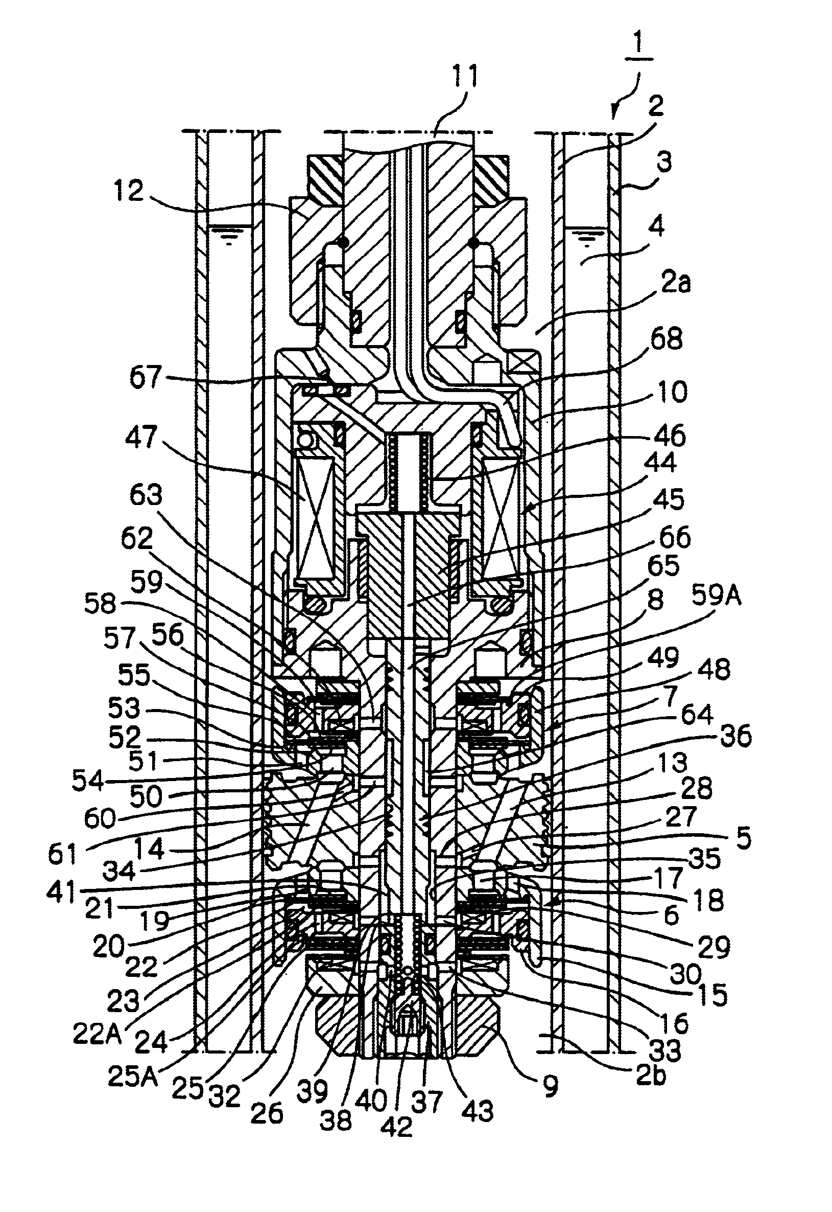
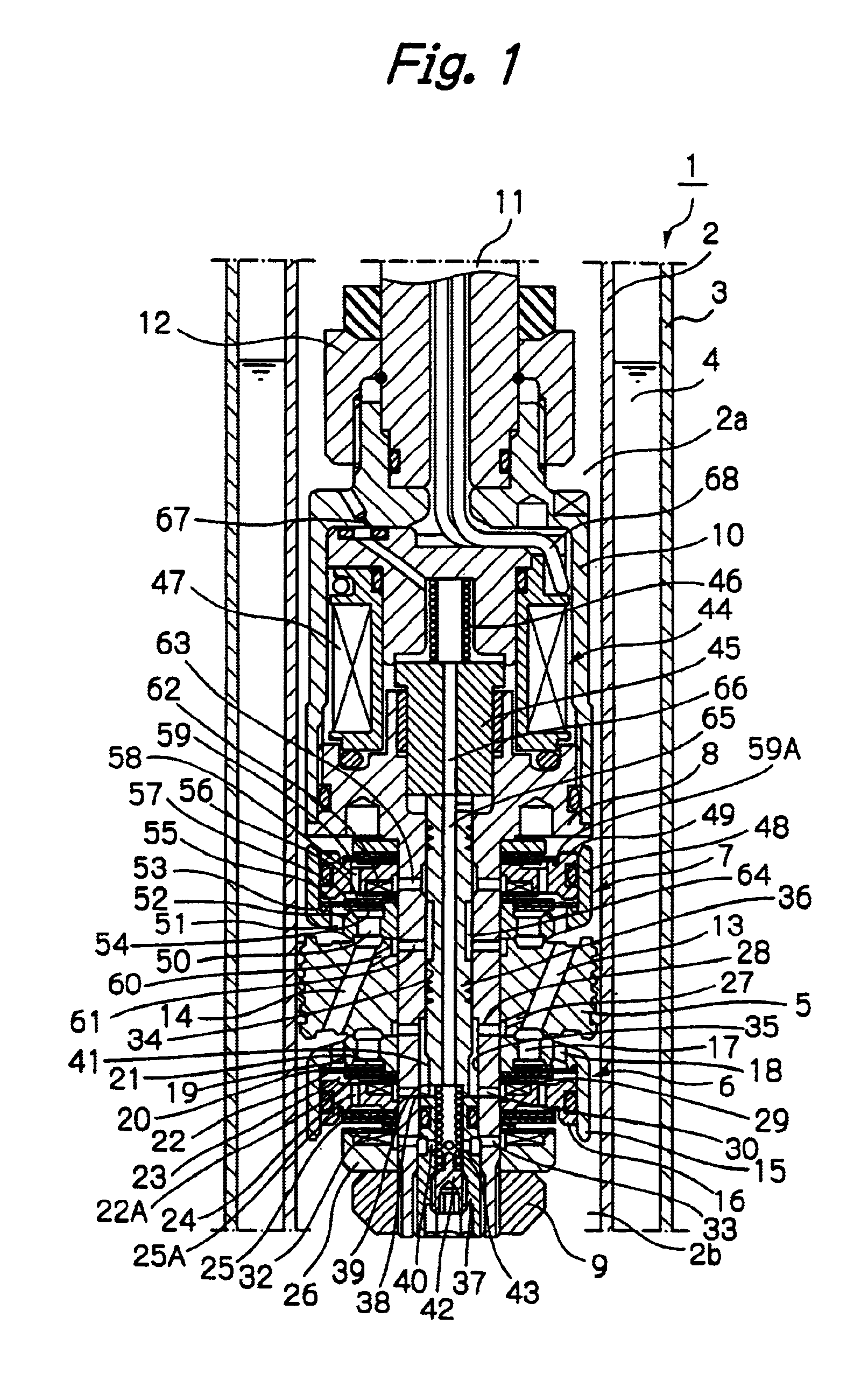
A solenoid case 10 is threadably engaged with a large-diameter proximal end portion of the piston bolt 8. An end portion of a piston rod 11 is connected to the solenoid case 10 by means of a nut 12. The other end portion of the piston rod 11 extends through the upper cylinder chamber 2a, and a rod guide (not shown) and an oil seal (not shown) provided on an upper end of the cylinder 2 and the outer cylinder 3 to the outside of the cylinder 2. A base valve (not shown) is provided at a lower end portion of the cylinder 2. The base valve permits communication between the lower cylinder chamber 2b and the reservoir 4 with an appropriate flow resistance. A hydraulic fluid is sealably contained in the cylinder 2, and a hydraulic fluid and a gas are sealably contained in the reservoir 4.

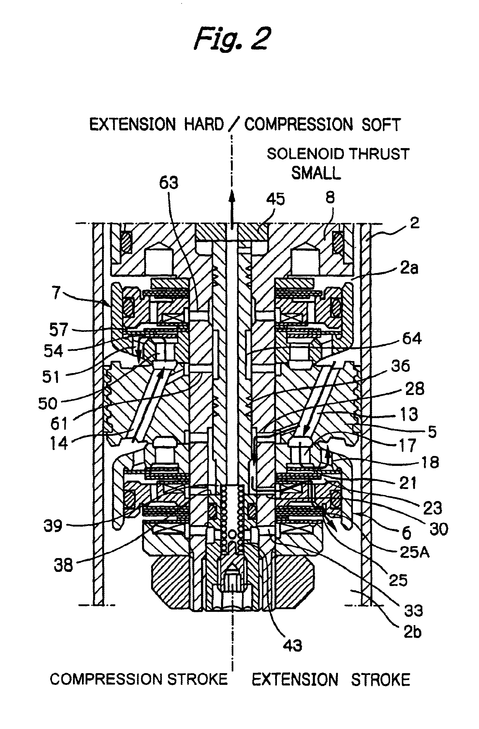
An extension-stroke passage 13 and a compression-stroke passage 14 are formed in the piston 5 so as to permit communication between the upper cylinder chamber 2a and the lower cylinder chamber 2b.

The exten...


PUM


Abstract

A piston having a piston rod connected thereto is slidably fitted in a cylinder in which a hydraulic fluid is sealably contained. Extension-stroke and compression-stroke pilot type damping force control mechanisms are provided in the piston. Check valves are provided at inlet openings of back-pressure chambers (pilot chambers). Relief valves provided in the pilot chambers include orifice passages. When the direction of stroke of the piston rod is reversed, the pressures in the back-pressure chambers are maintained due to the check valves, and the back-pressure chambers are pressurized to a satisfactory level through the orifice passages.

Description

BACKGROUND OF THE INVENTIONThe present invention relates to a controllable damping force hydraulic shock absorber which is mounted on a suspension apparatus of a vehicle such as an automobile.As a hydraulic shock absorber mounted on a vehicle such as an automobile, there is known a controllable damping force hydraulic shock absorber in which damping force characteristics can be appropriately controlled according to road surface conditions, vehicle running conditions, etc., so as to improve ride comfort and steering stability.Generally, a controllable damping force hydraulic shock absorber is arranged as follows. A piston, which has a piston rod connected thereto to form a piston assembly, is slidably fitted into a cylinder in which a hydraulic fluid is sealably contained. The piston divides the inside of the cylinder into two chambers. The piston assembly is provided with a main hydraulic fluid passage and a bypass passage which permit communication between the two chambers in the c...

Claims


Application Information

Patent Timeline
IPC IPC(8): F16F9/46F16F9/34F16F9/348F16F9/44F16F9/16F16F9/32
CPCF16F9/3485F16F9/466F16F9/461F16F9/16
Inventor NAKADATE, TAKAO
Owner HITACHI ASTEMO LTD
Why Eureka
Try Eureka