Fence dispensing apparatus

a technology for dispensing apparatuses and fences, applied in fencing wires, hoisting equipment, other domestic objects, etc., can solve the problems of inefficient operation, lack of safety features, and difficulty in setting up of dispensing apparatuses, so as to improve overall efficiency and improve overall efficiency

Inactive Publication Date: 2005-03-01
ALBRITTON SANDERFORD FENCE CO
View PDF16 Cites 11 Cited by
  • Summary
  • Abstract
  • Description
  • Claims
  • Application Information

AI Technical Summary

Benefits of technology

It is another object of the present invention to provide a new and improved fence dispensing apparatus that improves the overall efficiency in which wire is dispensed by an apparatus pulled behind a vehicle.
Furthermore, it is an object of the present invention to provide a fence dispensing apparatus that has a replaceable wear plate. The wear plate protects the base member from excessive wear as the fence unrolls from the spindle, making the apparatus more durable.
Lastly, it is an object of the present invention to provide a fence dispensing apparatus that improves the overall efficiency in which unrolled wire is stretched.

Problems solved by technology

However, the existing fence dispensing apparatuses are difficult to set up, lack sufficient safety features, and operate inefficiently.
Additionally, the existing apparatuses inefficiently stretch unrolled wire.
Pierre '234 patent does not disclose a wire dispensing apparatus that is easy to set up, and has a further drawback of operating inefficiently.
This is a major drawback as wire rolls often weigh up to five hundred pounds.
Additionally, the wire sits on a base plate that experiences excessive wear as the wire unrolls from the spindle.
Because the spindle is welded to the base plate, a worn base plate is both difficult and expensive to replace.
However, the Smith '216 patent lacks a surface between the ground and its separator plates.
This is a drawback because fences are often erected in fields containing loose brush and debris.
Loose brush and debris may entangle themselves in the rolled wire, impeding the wire from dispensing efficiently.
Lastly, U.S. Pat. No. 6,419,182 to Jimmy Jansky discloses a wire dispensing unit that operates unsafely and inefficiently.
The Jansky '182 patent does not permit a roll of wire to be secured to the apparatus, thus it cannot properly insure that wire stays on its spindle as it unrolls.
This is a safety concern because the wire may injure someone if it ejects from the dispensing unit.
Furthermore, this is an efficiency concern because it takes time to reload the wire roll each time it ejects from the spindle.
Additionally, none of the aforementioned apparatuses efficiently stretch unrolled wire.
While the above-described devices fulfill their respective, particular objectives and requirements, the aforementioned patents do not describe a fence dispensing apparatus that allows easy loading and safe, efficient operation.
Pierre apparatus is both dangerous and time consuming.
This is a drawback because obstructions may entangle themselves in the rolled wire, impeding the wire from dispensing efficiently.
The Jansky apparatus is unsafe because a wire roll may eject itself and harm someone.
Moreover, having to stop and reload a wire roll each time it ejects is inefficient.

Method used


Image

  • Fence dispensing apparatus
  • Fence dispensing apparatus
  • Fence dispensing apparatus

Examples


Embodiment Construction

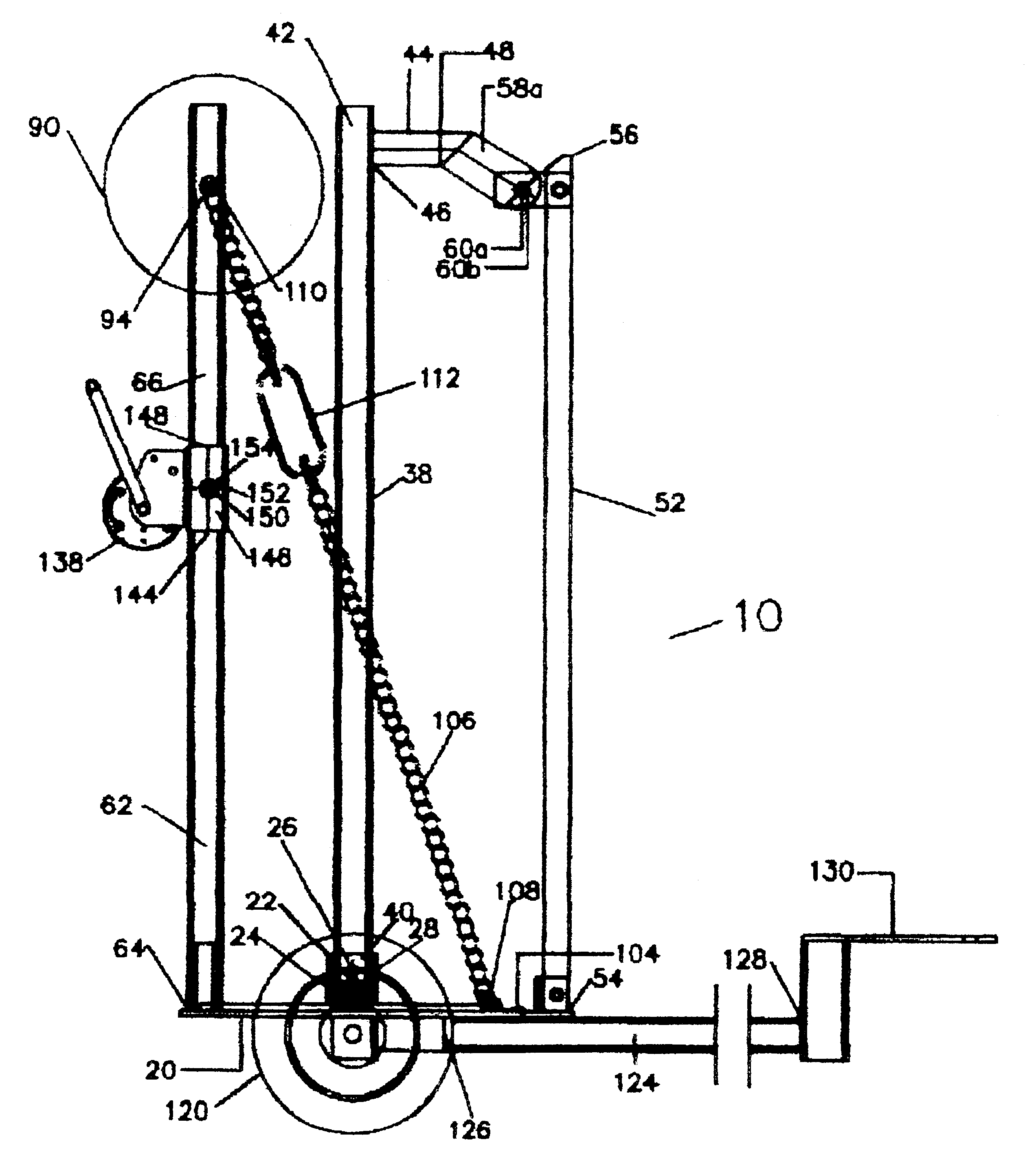
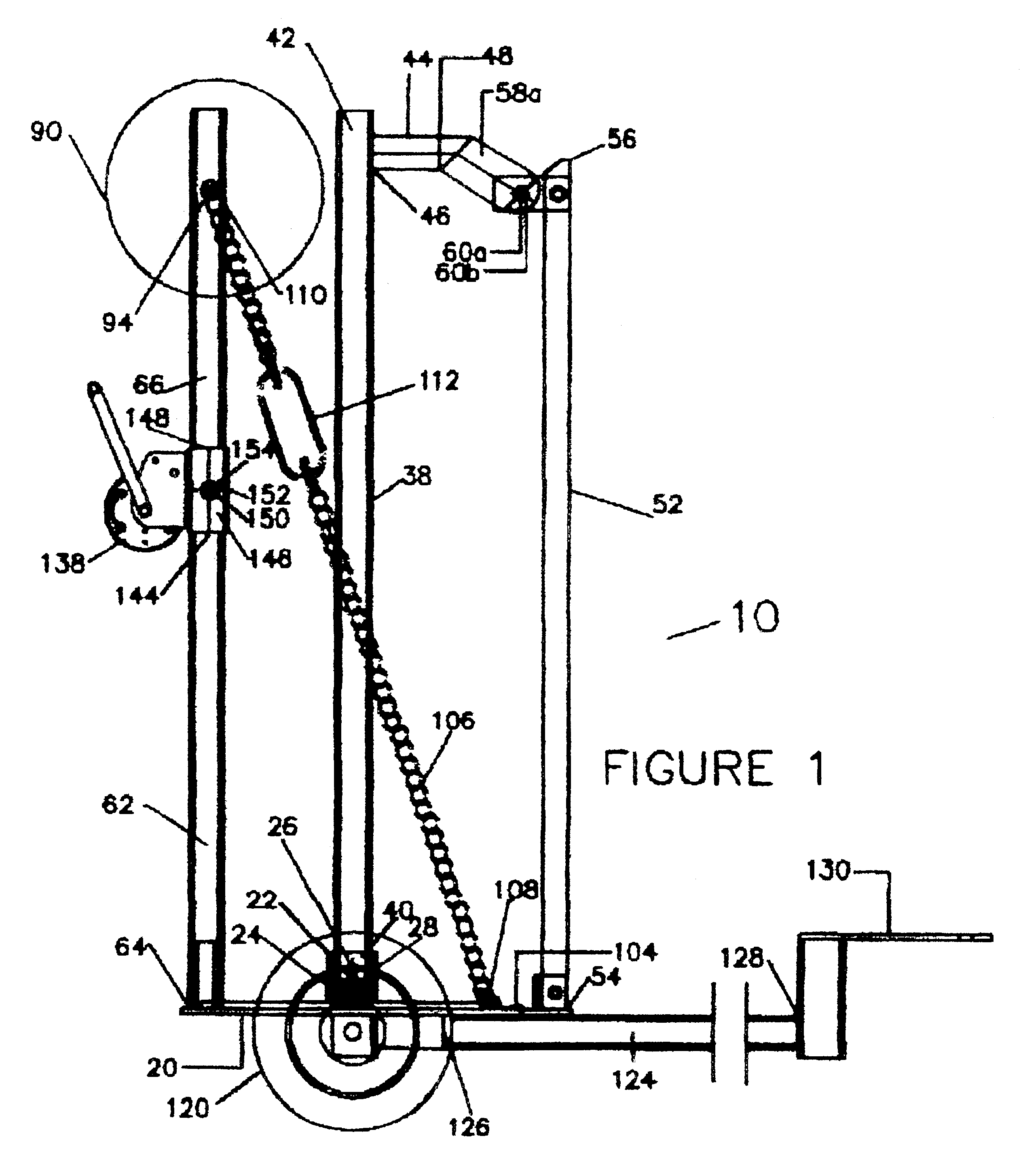
Referring now to the drawings, and particularly to FIGS. 1-6, a preferred embodiment of the fence dispensing apparatus of the present invention is shown and generally designated by the reference numeral 10.

In FIG. 1, a new and improved fence dispensing apparatus 10 of the present invention for easily, efficiently, and safely dispensing fencing wire along a line of fence posts is illustrated and will be described. More particularly, the fence dispensing apparatus 10 has a base member 12 that functions as the fence dispensing apparatus' main body and support. The base member 12 further comprises a front end 14, a back end 16, a top surface 18, and a bottom surface 20. The front end 14 moves forward down a line of fence posts while wire unrolls off the back end 16. In the preferred embodiment, the base member 12 has a rectangular shape.

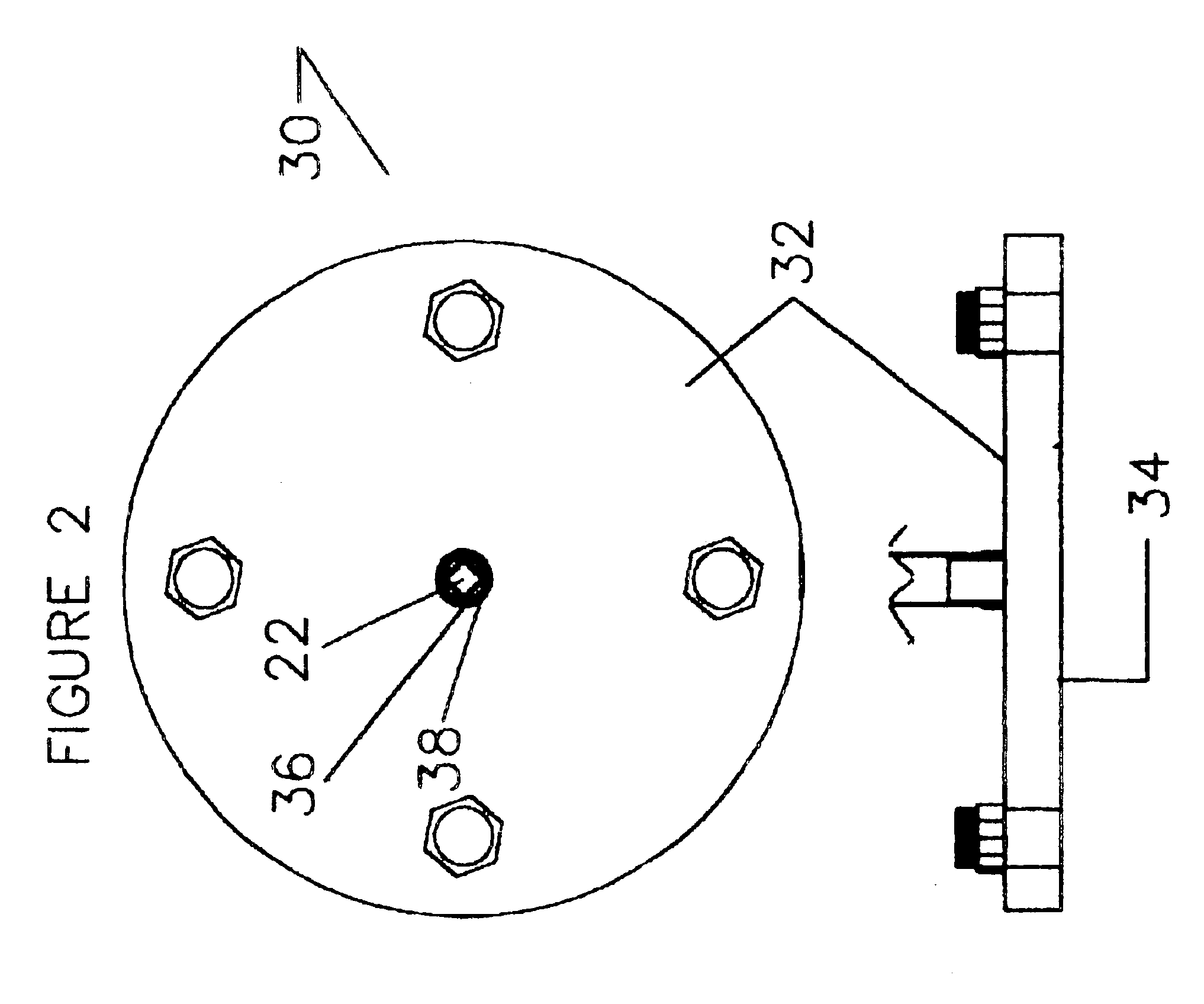
A spindle receptacle 22 is fixed to the base member 12, extending perpendicularly from the top surface 18. Additionally, the spindle receptacle 22 compr...


PUM


Abstract

A fence dispensing apparatus for installing fencing wire along a line of fence posts. The fence dispensing apparatus permits easy setup along with efficient and safe operation. In addition to dispensing wire, the apparatus stretches unrolled wire using a winch and a wire interface. The fence dispensing apparatus essentially comprises a base member that sits on an axle and wheels. Moreover, the base member connects to a motor vehicle via a hitch receiver or a three-point tractor hookup. As the vehicle travels along a fence line, the apparatus dispenses wire from a vertically aligned spindle and/or from a horizontally aligned roller. The spindle disconnects from the base member, permitting it to be easily loaded with wire and set up for operation. Additionally, a spindle lock and spindle support act in concert to safely hold the loaded spindle in position. Furthermore, a wear plate between the loaded spindle and the base member protects the base member from excessive wear during operation. In addition to the spindle, a horizontally aligned roller dispenses wire. The horizontal roller includes a safety plate that protects against injury if the unrolled wire breaks and backlashes. Unrolled wire may be connected to a wire interface, permitting the unrolled wire to be associated to a cable without cutting the wire. Turning the apparatus' winch reels in the cable, stretching the unrolled wire.

Description

BACKGROUND OF THE INVENTION1. Field of the InventionThe present invention relates to a fence dispensing apparatus for use in connection with installing fencing wire along a line of fence posts. The fence dispensing apparatus has particular utility in connection with promoting safe and efficient unrolling of fencing wire. The fence dispensing apparatus has further utility in permitting fast and easy setup for operation. Additionally, the apparatus stretches unrolled fence.2. Description of the Prior ArtFence dispensing apparatuses facilitate unrolling of fencing wire along a line of fence posts. In fact, the fence installing art is crowded with various apparatuses that dispense fencing wire. However, the existing fence dispensing apparatuses are difficult to set up, lack sufficient safety features, and operate inefficiently. Additionally, the existing apparatuses inefficiently stretch unrolled wire.For example, U.S. Pat. No. 5,476,234 to Bertin J. St. Pierre discloses a vehicle-mount...

Claims


Application Information

Patent Timeline
Patent Type & Authority Patents(United States)
IPC IPC(8): B65H49/00B65H49/32E04H17/26
CPCB65H49/32E04H17/266B65H2701/364
Inventor ALBRITTON, SAMUEL H.
Owner ALBRITTON SANDERFORD FENCE CO
Why Eureka
Try Eureka