Clock deskew protocol using a delay-locked loop

a delay-locked loop and clock technology, applied in the field of clock deskewing, can solve the problems of non-ideal skew between data transmission and clock signal, limited maximum reliable transmission speed between transmitter and receiver, and non-ideal skew

Inactive Publication Date: 2005-03-01
NAT SEMICON CORP
View PDF4 Cites 63 Cited by
  • Summary
  • Abstract
  • Description
  • Claims
  • Application Information

AI Technical Summary

Problems solved by technology

A non-ideal skew may occur between the data transmission and the clock signal.
The non-ideal skew is often the result of transmission dissimilarities between the clock and data signals because of various transmission characteristics.
Example transmission characteristics that are problematic may include signal routing geometry, length of the signal lines, impedance of the signal lines, loading on the signal lines, as well as differences in the delay paths of the clock and data signals for the transmitter and receiver.
The maximum reliable transmission speed between the transmitter and receiver is limited by the clock / data skew characteristics.

Method used


Image

  • Clock deskew protocol using a delay-locked loop
  • Clock deskew protocol using a delay-locked loop
  • Clock deskew protocol using a delay-locked loop

Examples


example protocol

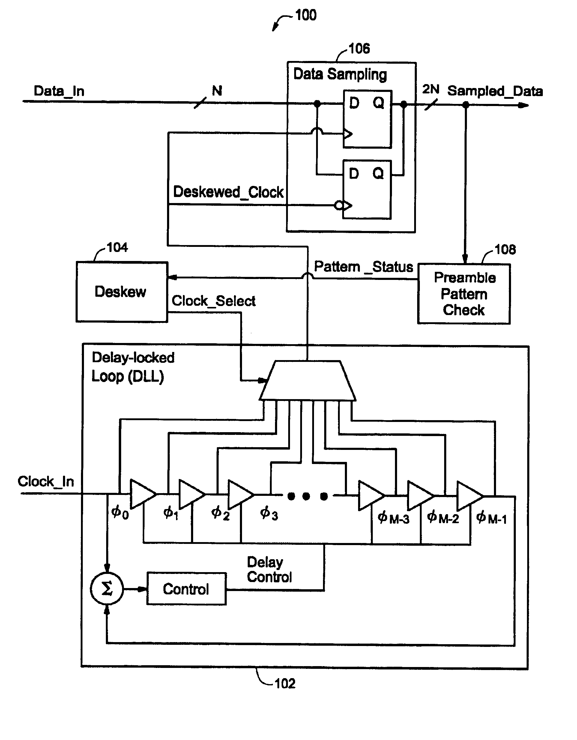
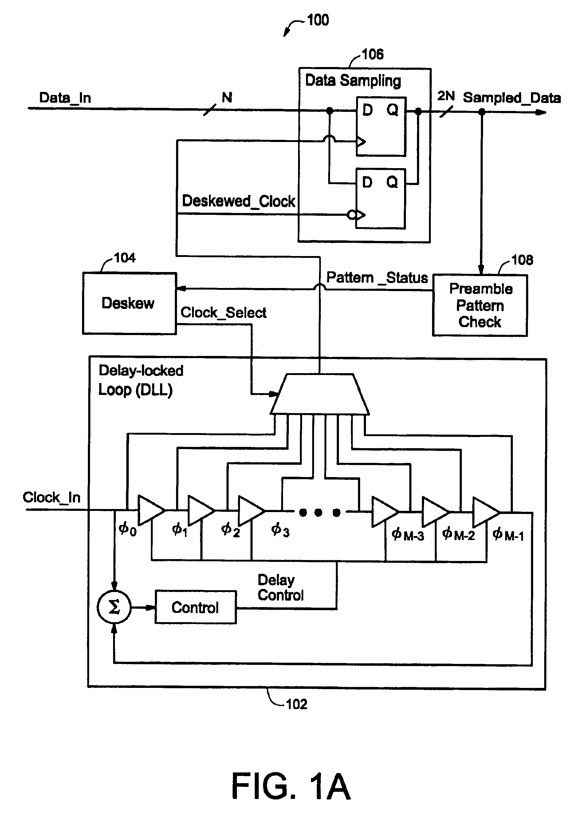
FIG. 3 is an illustration of a timing diagram for an example data frame protocol. As described previously, the system is operated over two basic time intervals that makeup the data frame transmission cycle.

An adjustment time interval is utilized to attend to various overhead and synchronization of the sampling clock prior to “live” data sampling. The “live” data sampling is subsequently performed in a data sampling time interval. The overhead portion of the adjustment time interval can be used for various configuration functions. An example system may have an adjustment time interval that comprises 5% of the data frame transmission cycle. Other example systems may comprises more or less than 5% of the data frame transmission cycle.

The example data protocol illustrated in FIG. 3 includes an adjustment time interval that is broken into three constituent parts: a Header interval, an Execute Deskew interval, and a DLL Loop Update interval. The DLL Loop Update interval may be used by cir...

example deskew

Methodology

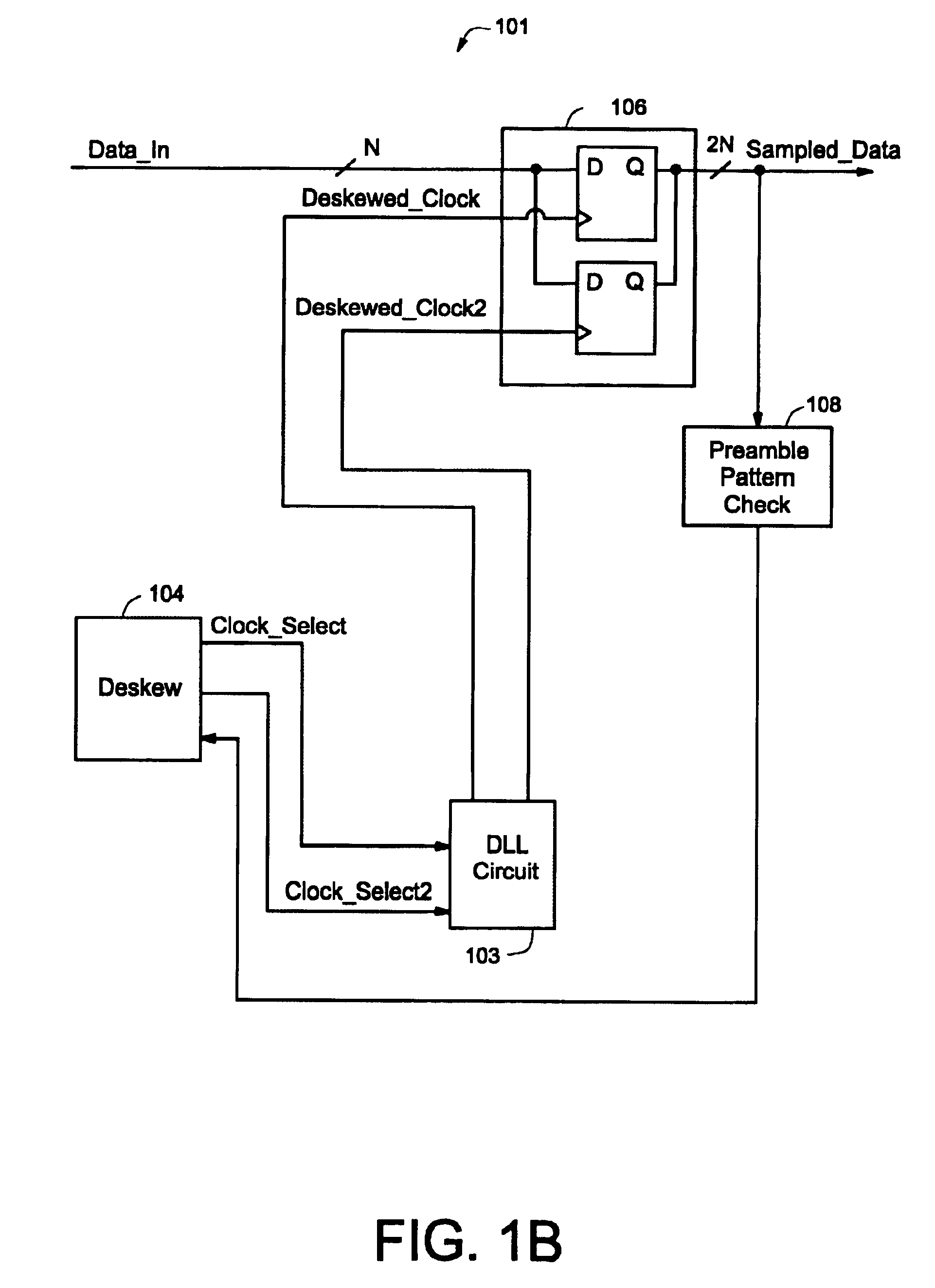
FIG. 5 is an illustration of a flow diagram (500) for an example deskewing methodology. The methodology is broken into three phases: a skew checking phase (501), a failure checking phase (502), and a clock selection phase (503).

The skew checking phase (501) is performed for each of the available clock signals (i.e., the clock phases) during different Execute Deskew intervals. During the skew checking phase, data is sampled using the selected clock signal, and the sampled data is compared to the desired preamble pattern for accuracy. The skew checking phase also decides which clock signals correspond to the first and last passing phases for the sampled data. The failure checking phase (502) is arranged to reevaluate the last selected clock signal and decide whether the system is properly operating as a failsafe check. The clock selection phase (503) is arranged to select the appropriate clock signal based on historical data and the results of the skew checking phase (501) ...

example midpoint

Filtering Methology

Processing for the example midpoint filtering method begins at start block 602. Processing then proceeds from start block 602 to block 604. At block 604, FILTER_COUNT is initialized to zero. Processing then proceeds from block 604 to block 606. At block 606, process 548 waits for the end of the DDA cycle. Processing then proceeds from block 606 to decision block 608. At decision block 608, process 548 evaluates whether MIDPOINT is greater than DESKEW_PHASE. Processing proceeds from decision block 608 to decision block 610 when MIDPOINT is greater than DESKEW_PHASE. Alternatively, processing proceeds from decision block 608 to decision block 615 when MIDPOINT is not greater than DESKEW_PHASE. At decision block 615, process 548 evaluates whether MIDPOINT is less than DESKEW_PHASE. Processing proceeds from decision block 615 to decision block 616 when MIDPOINT is less than DESKEW_PHASE. Alternatively, processing proceeds from decision block 615 to decision block 622 ...


PUM


Abstract

A data/clock deskewing methodology uses a delay-locked loop (DLL) circuit. The DLL circuit generates a number of clock phases in response to an input clock, where each clock phase is delayed relative to the input clock signal. The clock phases are used to sample data from a data line. The sampled data is checked against a preamble pattern (a sequence of known data). A digital deskew control block selects one of the clock phases after analyzing the results of preamble pattern check such that subsequently received data is sampled with the appropriately selected clock phase.

Description

FIELD OF THE INVENTIONThe present invention relates to clock deskewing, and, in particular, to a method and apparatus for clock deskewing by using a delay-lock loop (DLL) circuit that provides multiple clock phases for selection. A data line is sampled using a selected clock phase. The sampled data is compared to a preamble pattern to determine an appropriate clock phase for the data that follows.BACKGROUND OF THE INVENTIONA conventional electronic system may employ a receiver and transmitter pair to send data that is synchronized with a clock signal. A non-ideal skew may occur between the data transmission and the clock signal. The non-ideal skew is often the result of transmission dissimilarities between the clock and data signals because of various transmission characteristics. Example transmission characteristics that are problematic may include signal routing geometry, length of the signal lines, impedance of the signal lines, loading on the signal lines, as well as differences...

Claims


Application Information

Patent Timeline
Patent Type & Authority Patents(United States)
IPC IPC(8): H03L7/06H03L7/081H04L7/00H04L7/10
CPCH03L7/0812H04L7/0037H04L7/10H04L7/0008
Inventor LUDDEN, CHRISTOPHER A.ERHART, RICHARD ALEXANDERKUHNS, MARK D.ALAM, ARIF
Owner NAT SEMICON CORP
Why Eureka
Try Eureka