Eureka AIR delivers breakthrough ideas for toughest innovation challenges, trusted by R&D personnel around the world.

Squaring cells and multipliers using summed exponentials

a technology of exponentials and multipliers, applied in the field of rms-dc converters, can solve the problems of inability to provide an rms response in logarithmic amplifiers, and difficulty in performing accurate rms-dc conversions over a wide dynamic rang

Inactive Publication Date: 2005-03-01
ANALOG DEVICES INC
View PDF12 Cites 16 Cited by
  • Summary
  • Abstract
  • Description
  • Claims
  • Application Information

AI Technical Summary

Benefits of technology

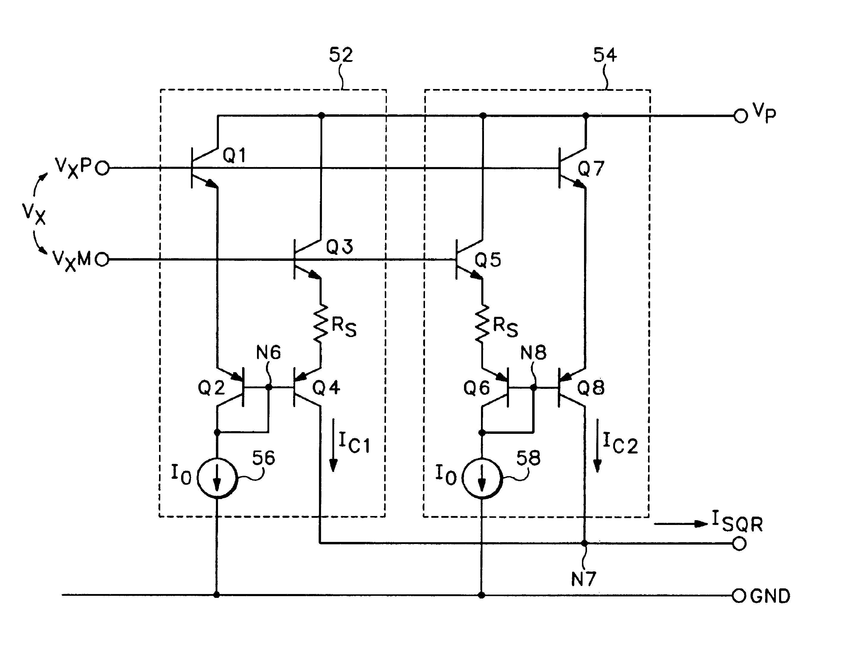
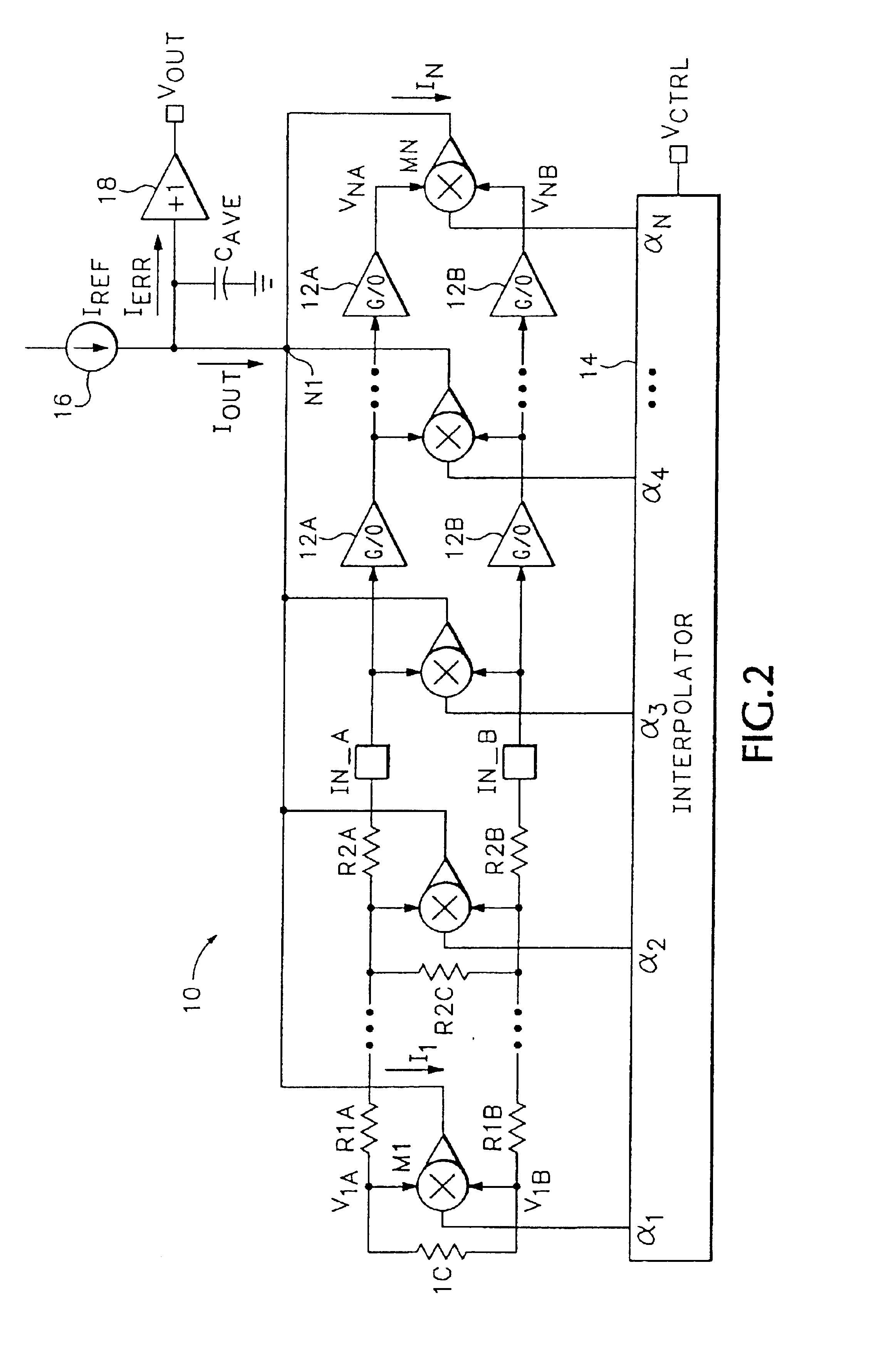
In one aspect of the present invention, a series of cascaded gain stages generate a series of progressively amplified signals, which are squared and weighted and then summed to provide a true square-law response. In another aspect of the present invention, two parallel series of cascaded gain stages generate a series of progressively amplified signal pairs, which are multiplied and weighted and then summed to provide a true square-law response while also canceling uncorrelated noise. In a further aspect of the present invention, two signals are generated by exponential signal generators responsive to an input signal, and combined to provide an output signal, which approximates the squared value of the input signal. In another aspect of the present invention, four signals are generated by exponential signal generators responsive to two input signals, and combined to provide an output signal, which approximates the multiplication of the input signals. In an additional aspect of the present invention, an exponential signal is generated responsive to an input signal by maintaining a constant current in a first pair of series-connected junctions, thereby generating a first voltage across the first pair of junctions; and driving a second pair of series-connected junctions with a voltage equal to the first voltage minus the voltage of the signal.

Problems solved by technology

Performing accurate RMS-DC conversions over a wide dynamic range has proven difficult, especially at RF frequencies of several GHz.
However, logarithmic amplifiers, including synchronous log amps, do not provide an RMS response.

Method used


Image

  • Squaring cells and multipliers using summed exponentials
  • Squaring cells and multipliers using summed exponentials
  • Squaring cells and multipliers using summed exponentials

Examples


Embodiment Construction

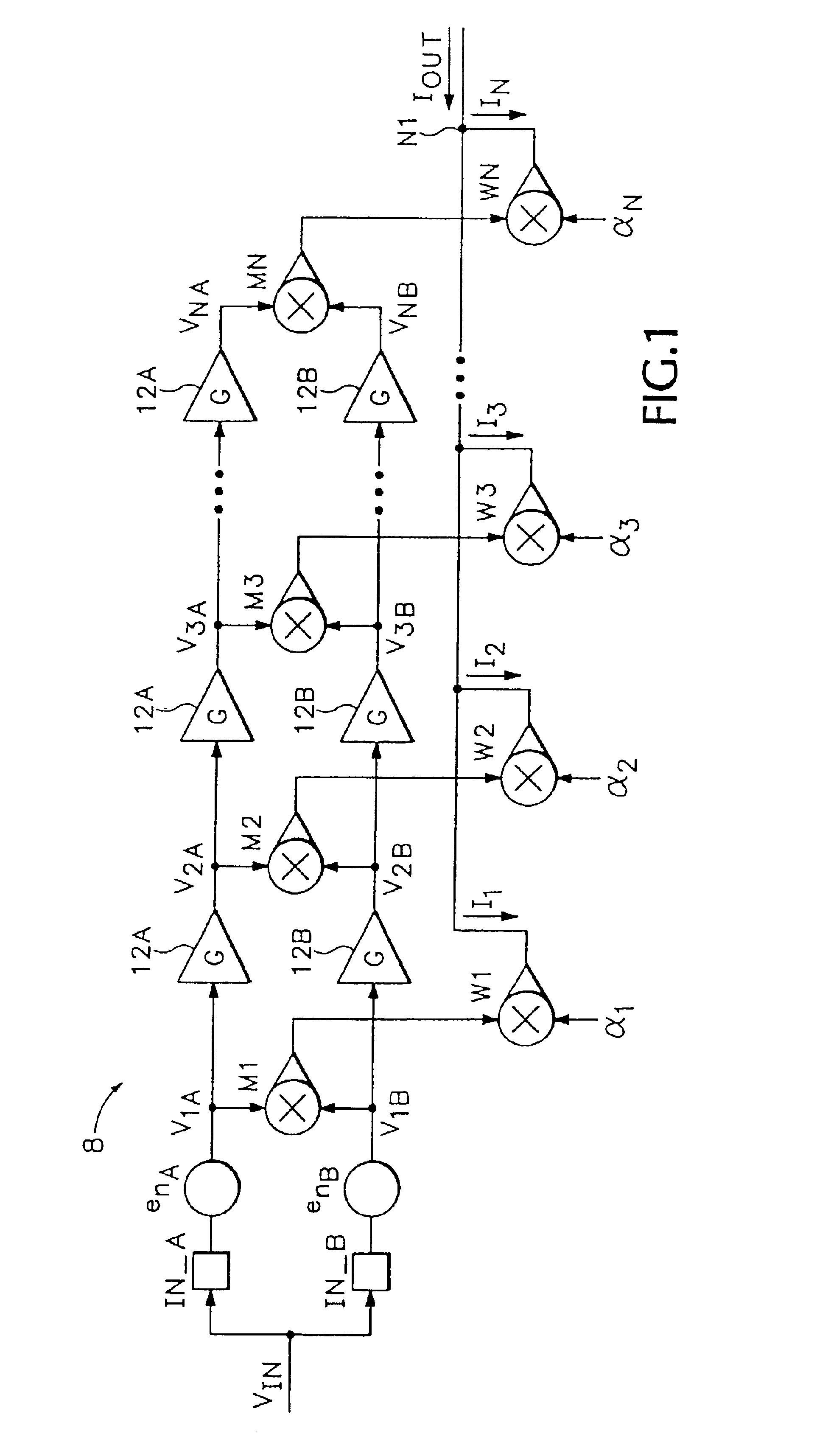
FIG. 1 is a simplified schematic of an embodiment of a backbone of an RMS-DC converter 8 in accordance with the present invention. The system of FIG. 1 includes a first chain or series of gain stages 12A, a second series of gain stages 12B, a first series of four quadrant multipliers M1, M2, . . . MN, and a second series of weighting multipliers W1, W2, . . . WN which only need to operate in two quadrants.

The first series of gain stages are connected in a cascade arrangement and generate a first series of progressively amplified signals VkA (k=1 . . . N) in response to the input voltage VIN. Likewise, the second series of gain stages generate a second series of progressively amplified signals VkB (k=1 . . . N) in response to VIN. The signals V1A and V1B are simply the input voltage VIN (plus the noise from sources enA and enB as described below). The first series of multipliers are coupled to the first and second series of gain stages so that each multiplier Mk generates an output s...


PUM


Abstract

A squaring cell combines first and second exponential currents to approximate square law behavior. The exponential currents can be generated by current stacks having pairs of series-connected junctions. The exponential currents can be altered to change the shape of the exponential currents to better approximation true square law behavior. A multiplier combines four exponential currents to approximate a multiplication function. The exponential currents in the multiplier can be generated by current stacks that are cross-connected so as to generate two output currents, the difference of which represents the multiplication of two input signals.

Description

BACKGROUND OF THE INVENTION1. Field of the InventionThe present invention relates generally to RMS-DC converters, and more particularly, to RMS-DC converters, which utilize gain stages and variable weighting coefficients to provide a very wide measurement range.2. Description of the Related ArtRMS-DC converters are used to convert the RMS (root-mean-square) value of an arbitrary signal into a quasi-DC signal that represents the true power level of the signal. Various techniques have been devised for performing RMS-to-DC conversions at frequencies ranging from DC to several GHz, some of which are disclosed in co-pending U.S. patent application Ser. No. 09 / 245,051 filed Feb. 4, 1999, which is now U.S. Pat. No. 6,204,719, and Ser. No. 09 / 256,640 filed Feb. 24, 1999, which is now U.S. Pat. No. 6,172,549, which are by the same inventor as the present application, and are incorporated herein by reference.Performing accurate RMS-DC conversions over a wide dynamic range has proven difficult...

Claims


Application Information

Patent Timeline
Patent Type & Authority Patents(United States)
IPC IPC(8): G01R19/02G05F3/22G05F3/26H03G1/00
CPCG01R19/02H03G1/0088G05F3/265G05F3/222
Inventor GILBERT, BARRIE
Owner ANALOG DEVICES INC
Why Eureka
Eureka Blog
Learn More