Laser light generating apparatus and method

Inactive Publication Date: 2005-03-01
SONY CORP
View PDF7 Cites 20 Cited by
  • Summary
  • Abstract
  • Description
  • Claims
  • Application Information

AI Technical Summary

Benefits of technology

[0020]A laser light generating method according to the present invention includes: inputting phase-modulated laser light to a first resonator and then inputting light generated by a nonlinear optical element disposed within the first resonator to a second resonator; and detecting light from the first resonator and light from the second resonator, generating an error signal from each of detection signals and a modulating signal, and thereby controlling length of an optical path of

Problems solved by technology

However, the conventional apparatus have the following problems.
The polarization method and the like therefore have a problem in stability.
However, such a modulator is difficult to obtain.
The FM sideband method has a disadvantage of increasing cost and power consumption and thus has a problem in terms of p

Method used


Image

  • Laser light generating apparatus and method
  • Laser light generating apparatus and method
  • Laser light generating apparatus and method

Examples


Embodiment Construction

ndence of relative reflectivity;

[0026]FIG. 5 is a graphical representation of δ dependence of relative transmissivity;

[0027]FIG. 6 is a diagram showing in enlarged dimension an important part of the δ dependence of the relative reflectivity;

[0028]FIG. 7 is a diagram showing δ dependence of an error signal;

[0029]FIGS. 8A, 8B, and 8C are diagrams of assistance in explaining a relation between frequency dependence of reflectivity and modulation frequency; and

[0030]FIG. 9 is a diagram showing another example of configuration according to the present invention.

DETAILED DESCRIPTION OF THE PREFERRED EMBODIMENT

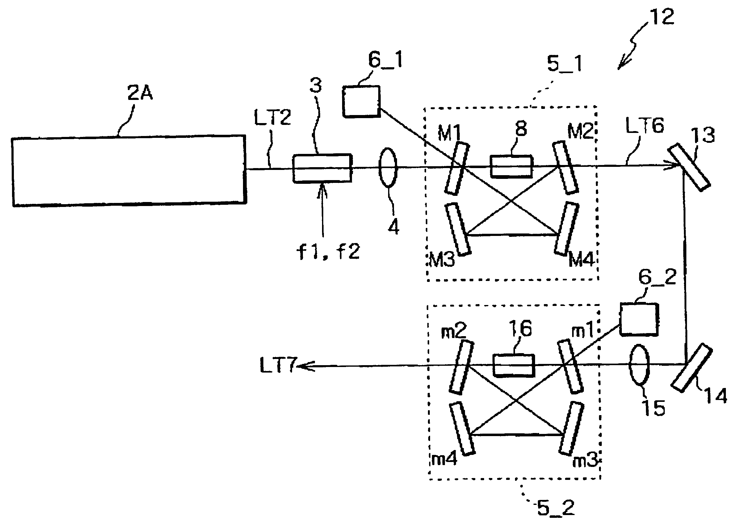
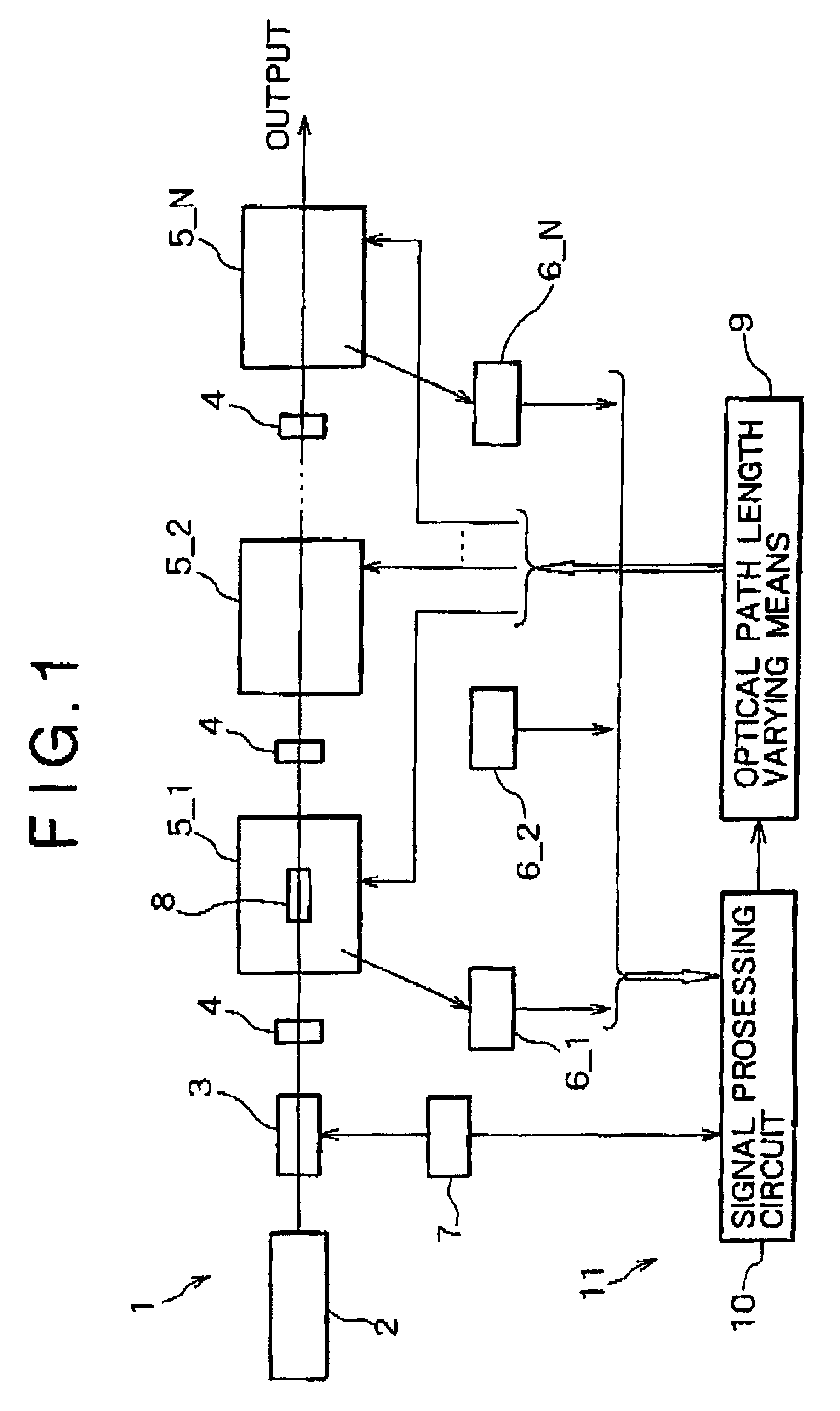
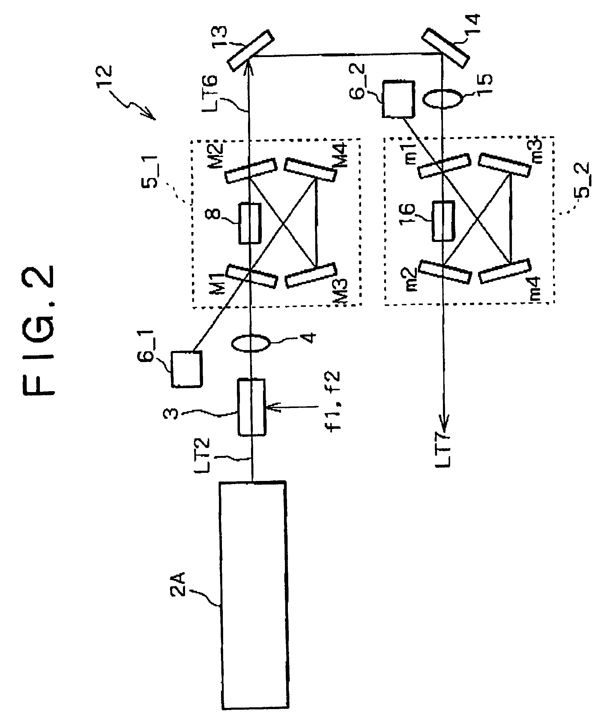
[0031]The present invention relates to a laser light generating apparatus using a continuous-wave (CW) capable laser light source and a plurality of resonators, and is suitable for application to wavelength conversion over a plurality of stages, for example.

[0032]FIG. 1 is a diagram of assistance in conceptually explaining an example of fundamental configuration of the present inventi...


PUM


Abstract

A laser light generating apparatus is provided with a laser light source, a phase modulator, a signal generating unit for applying a modulating signal to the phase modulator, and resonators. A nonlinear optical element is provided in the resonator, and an optical path length varying means for changing length of an optical path of each of the resonators is provided. Error signals are obtained using detection signals of photodetectors for receiving light from the resonators, respectively, and the optical path length varying means is controlled by a sideband method, whereby a control circuit having a negative feedback configuration for controlling length of the resonators is formed. Laser light is subjected to phase modulation and then inputted to the resonator, and light generated by the nonlinear optical element is inputted to the resonator so that the plurality of resonators are simultaneously held in a resonant state.

Description

BACKGROUND OF THE INVENTION[0002]The present invention relates to a technique for achieving stable locking using a cross modulation carrier in a laser light generating apparatus with a laser light source and a plurality of resonators.[0003]An FM sideband method (“Pound-Drever-Hall Locking” method) is known as a method for stable locking of a resonator in a laser light generating apparatus, and is widely used for the locking of an external resonator in a range of near-infrared light to visible light.[0004]In addition to this method, there is a method using polarization (see literature such as Hansch, Couillaud, optics Communications, 1980). For example, a locking method has been proposed which inputs laser light passed through a wave plate to a resonator, and obtains an error signal on the basis of detection signals of two beams in different polarized states from the resonator to thereby maintain a resonant state of the resonator.[0005]However, the conventional apparatus have the fol...

Claims


Application Information

Patent Timeline
IPC IPC(8): G02F1/35G02F1/37H01S3/10H01S3/109
CPCG02F1/3532G02F2001/3542G02F1/37G02F1/3534G02F1/3542
Inventor MASUDA, HISASHI
Owner SONY CORP
Why Eureka
Try Eureka