Spatial and temporal equalizer and equalization method

a technology equalization method, which is applied in the field of spatial and temporal equalizer, can solve the problems of extended time of convergence of tap coefficients, inability to achieve sufficient convergence, and computation complexity of tap coefficient calculation

Inactive Publication Date: 2005-03-01
NTT DOCOMO INC
View PDF13 Cites 14 Cited by
  • Summary
  • Abstract
  • Description
  • Claims
  • Application Information

AI Technical Summary

Benefits of technology

It is therefore an object of the present invention to provide a spatial and temporal equalizer that permits optimum convergence of tap coefficients without significantly increasing computational complexity, and an equalization method therefor.
With the provision of the receiving quality estimating means, it is possible to decide whether the tap coefficients are sufficiently converged, and hence the convergence operation can be conducted until the tap coefficients are sufficiently converged.

Problems solved by technology

With the configuration of FIG. 10, the total number of taps of the feed forward filters F1 to FL is so large that the computational complexity for the tap coefficient calculation by the tap coefficient calculating part 13 increases, giving rise to the problem of extended time of convergence of the tap coefficients.
With this arrangement, however, in the case of estimating all the tap coefficients at the same time, no sufficient convergence can be achieved since the tap coefficients for the multipliers M1 to ML of the adaptive array antenna 10 and the tap coefficients of the feed forward filter 14 are provided in the form of product.
In the FIG. 10 example for batch processing as mentioned above, since each element of the adaptive array antenna 10 has the feed forward filter FFF, an increase in the number of antenna elements causes a dramatic increase in the total number of taps, and computational complexity increases accordingly.
This constitutes a serious obstacle to forming the spatial and temporal equalizer by hardware, and hence makes it impossible to implement the equalizer.
Further, since the convergence of the tap coefficients requires a long training signal period, the transmission efficiency is appreciably low.
Besides, since the feed forward filter 14 is in the simply-pass state during the tap coefficient convergence of the adaptive array antenna 10, no sufficient convergence can be achieved if symbol timing offset occurs.

Method used


Image

  • Spatial and temporal equalizer and equalization method
  • Spatial and temporal equalizer and equalization method
  • Spatial and temporal equalizer and equalization method

Examples


first embodiment

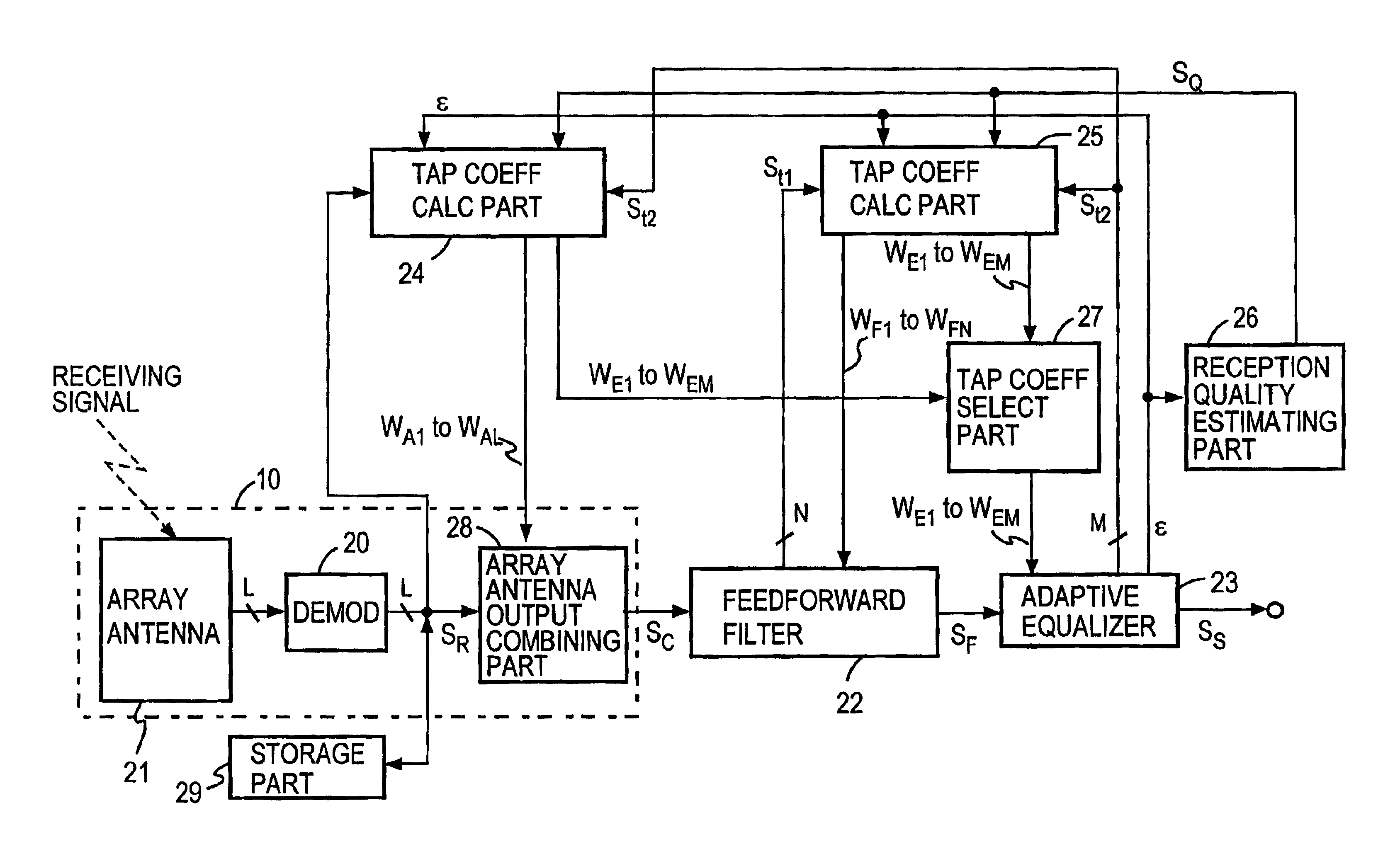
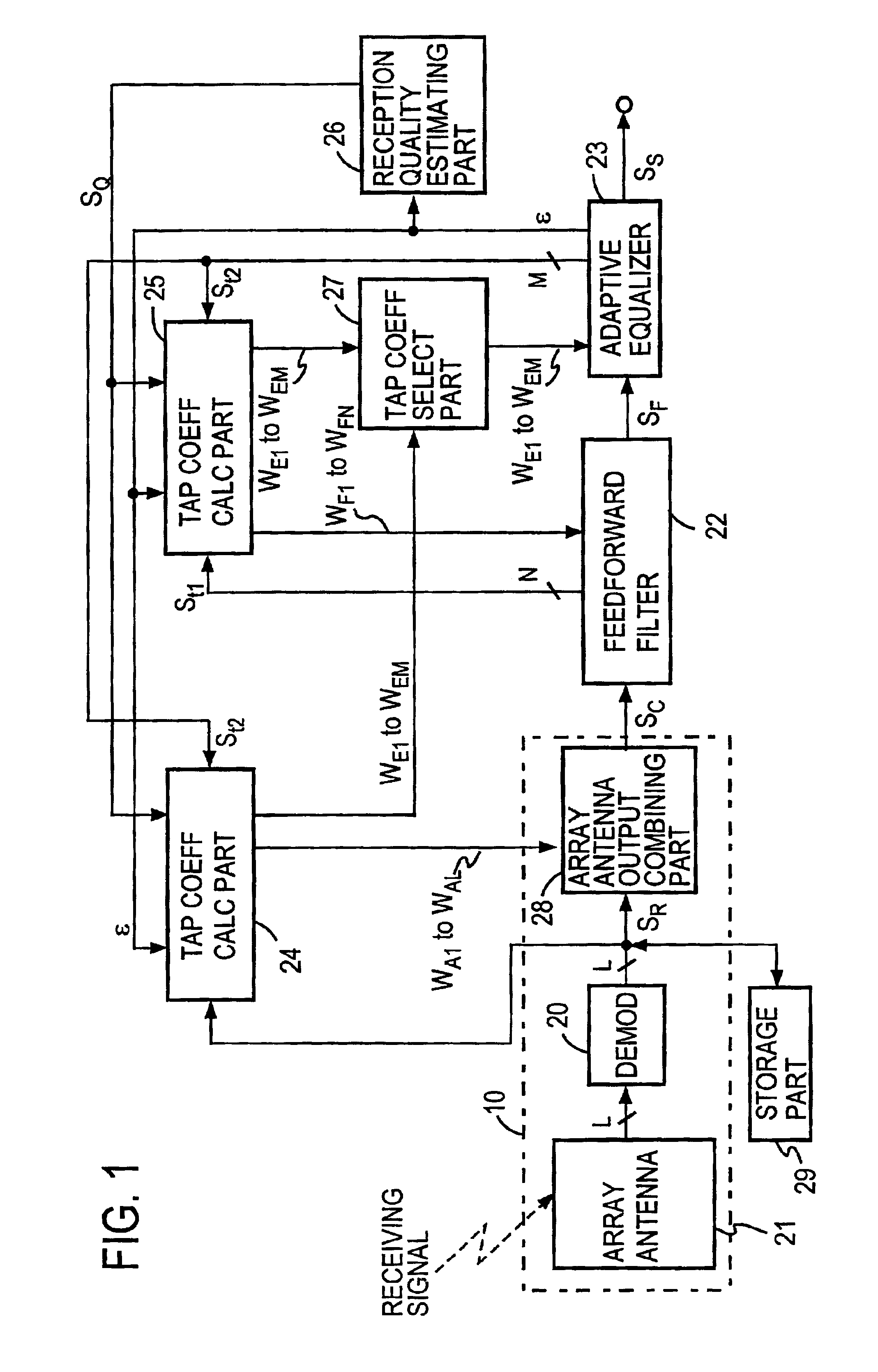
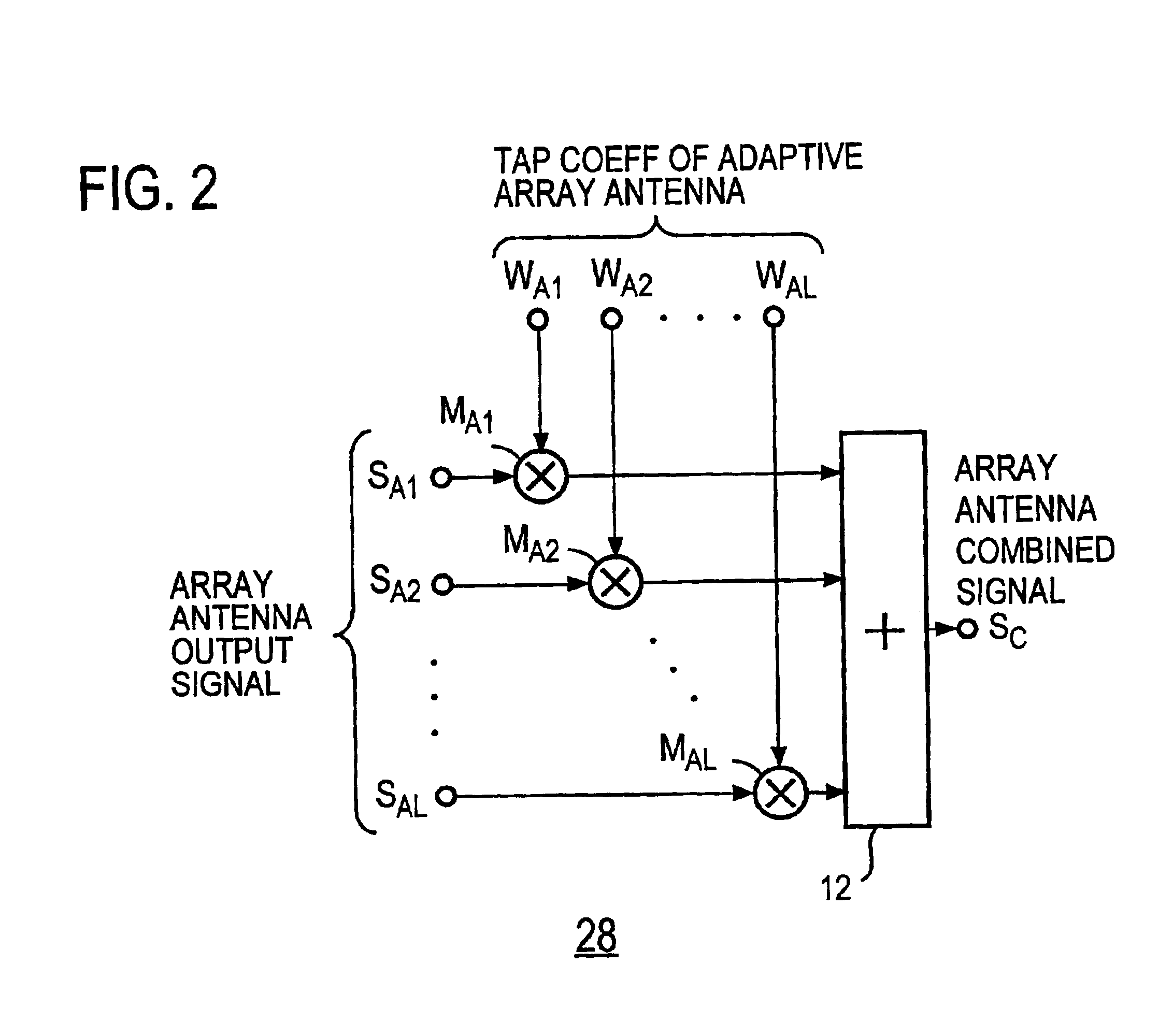
FIG. 1 illustrates in block form a first embodiment of the spatial and temporal equalizer according to the present invention, which is an improvement of the prior art described previously with reference to FIG. 11. Hence, the equalizer of this embodiment basically includes an adaptive array antenna 10, a feed forward filter 22, an adaptive equalizer 23 and tap coefficient calculating parts 24 and 25 as is the case with the FIG. 11 prior art example. An array antenna 21 in the adaptive antenna array 10 corresponds to the antenna elements A1 to AL in FIG. 11, and array antenna output combining part 28 corresponds to the multipliers M1 to ML in FIG. 11 as described later on with respect to FIG. 2. The feed forward filter 22, the adaptive equalizer 23, and the tap coefficient calculating parts 24 and 25 correspond to the feed forward filter 14, the adaptive equalizer 11 and the tap coefficient calculating parts 16 and 17, respectively, in FIG. 11.

The spatial and temporal equalizer accor...

second embodiment

Usually, the symbol timing for demodulation is made to coincide with the timing of the leading wave of the received signal. In the MLSE type equalizer of FIG. 4A that achieves the most excellent receiving characteristic, the above-mentioned timing is taken as time 0 (i.e., current time point) and a replica signal is generated from a symbol candidates at time 0 and past or previous symbol candidates (−T, −2T, . . . ) for equalization.

However, when there is a synchronization error in the symbol timing regenerated at the demodulator side or when the receiving level of the delayed wave is remarkably higher than the receiving level of the leading wave, components of future symbols subsequent to the current symbol timing are contained as intersymbol interference in the received signal. Since such future symbol components are not contained in the replica signal that is generated in the equalizer, the estimation error increases and the receiving characteristic is degraded accordingly.

When t...

third embodiment

A decision feedback equalizer can be used as the adaptive equalizer 23 in the FIG. 1 embodiment. FIG. 9 illustrates an example of its configuration. In this instance, a fed-back version of the decided symbol signal is used in place of the symbol candidate signal used in the maximum likelihood estimation type equalizer. That is, a replica of delayed components of received symbols prior to the current received symbol is generated by a replica generator 32′, then the replica of the delayed components is subtracted by an adder 34A from the filtering output signal (received signal) SF fed from the feed forward filter 22, and it is decided by a decision device 42 whether the output from the adder 34A is 1 or 0.

This decision result is output as a decoded symbol, and it is input to a series circuit of unit delay elements DU1 to DUM-1 each having a delay time of one symbol period T. The output signals from the delay elements DU1 to DUM-1 are complex-multiplied by tap coefficients of adaptive...


PUM


Abstract

Outputs from respective elements of an array antenna 21 are demodulated, and the demodulated outputs are stored in storage means 29. The demodulated outputs are multiplied by tap coefficients of adaptive array antenna, then the multiplied outputs are combined by combining means 28, and the combined output is provided via a feed forward filter 22 to an adaptive equalizer 23, wherein it is equalized to obtain a decision symbol. During reception of a training signal the tap coefficients of adaptive array antenna and tap coefficients of the adaptive equalizer 23 are subjected to convergence processing by tap coefficient calculating means 24 so that an error signal becomes small, and then tap coefficients of the feed forward filter 22 and the adaptive equalizer 23 are subjected to convergence processing by tap coefficient calculating means 25 so that an error signal becomes small. Thereafter, the convergence processing by the means 24 and 25 is repeated, during which a training signal stored in storage means 29 is used, results of the immediately preceding convergence processing are used as initial values, and it is decided by receiving quality estimating means 26 whether the error signal has become sufficiently small relative to the received signal power.

Description

BACKGROUND OF THE INVENTIONThe present invention relates to a spatial and temporal equalizer that is a hybrid of an adaptive array antenna and an adaptive equalizer for mobile communications, and a spatial and temporal equalization method.The adaptive array antenna and the adaptive equalizer are effective in removing interference in mobile communications. The adaptive array antenna adaptively generates a beam pattern (a directional pattern) in which a beam of a relatively high antenna gain (the main lobe of the directional pattern) is directed toward the wave desired to receive and null of the directional pattern, for which the antenna gain is significantly low, are directed toward interference waves such as signals from other users. The adaptive array antenna performs spatial signal processing and is an effective means for eliminating interference waves of the same channel as that of the desired waves, that is, cochannel interference.The adaptive equalizer has been used to eliminat...

Claims


Application Information

Patent Timeline
IPC IPC(8): H04B3/04H04B3/14
CPCH04B7/086H04B3/145
Inventor TOMISATO, SHIGERUMATSUMOTO, TADASHI
Owner NTT DOCOMO INC
Why Eureka
Try Eureka