
Data aided symbol timing system for precoded continuous phase modulated signals

a data-aided symbol and timing system technology, applied in phase-modulated carrier systems, frequency-modulated carrier systems, digital transmission, etc., can solve the problems of limiting the performance of cpm systems, synchronizers often lose track during noisy communications, and the cost of a moderate increase in receiver complexity, so as to reduce design complexity and reduce the effect of bit error rate performance and non-degraded performan

Inactive Publication Date: 2005-03-01
THE AEROSPACE CORPORATION
View PDF13 Cites 21 Cited by
  • Summary
  • Abstract
  • Description
  • Claims
  • Application Information

AI Technical Summary

Benefits of technology

The present invention is directed to data aided synchronization in digital carrier phase and symbol timing synchronizers applicable to precoded continuous phase modulation (CPM) signal formats, such as in Gaussian minimum shift keying (GMSK) communications systems having, for example, a modulation index of ½ with a bandwidth time product (BT) of ⅕. The imbedded synchronizers enable simple implementations for data demodulation for CPM signals, such as GMSK signals with small BT values. Data aided tracking is applied in one form to symbol time tracking, and in another form, to carrier phase tracking. An advantage of the proposed data aided symbol timing synchronizer is the combination of both symbol timing tracking and data demodulation functions into an integrated process obviating the need for a separate data demodulator in the receiver. For example, for GMSK signals with BT values of ⅓ and larger, the data demodulation performance in the symbol timing synchronizer can provide optimum performance. An advantage of the data aided carrier phase synchronizer is the combination of both carrier phase tracking and data demodulation functions into one integrated process obviating a need for separate data demodulator in the receiver. For example, for GMSK signals with BT values of ⅓ and larger, the data demodulation performance provided by the carrier phase synchronizer can also be optimum.
These digital synchronizers are use to track the symbol timing or carrier phase of a continuous phase modulation signal received in the presence of noise with the receiver operating in a data demodulation mode. These synchronizers have a nondegraded bit error rate (BER) performance with reduced design complexity. The GMSK signal with a BT=⅕ can be used as a typical partial response CPM signal. The hardware implementation of such a GMSK receiver with both synchronizers can be modeled for providing simulated BER performance. With data precoding of the original data bit stream prior to transmission of the CPM signal, the synchronizers can function as serial demodulators that achieve absolute phase data detection. The data preceding and data aided synchronization approach for detecting symbol timing and carrier phase error is central to providing accurate symbol time and carrier phase tracking in the synchronizers with reduced design complexity. These and other advantages will become more apparent from the following detailed description of the preferred embodiment.

Problems solved by technology

The use of CPM signals in communications systems can potentially achieve significant improvement in both power and spectral efficiency over other conventional modulation techniques, at the cost of a moderate increase in receiver complexity.
Often, symbol time tracking and carrier phase tracking limit the performance of CPM systems.
These synchronizers often lose track during noisy communications.

Method used


Image

  • Data aided symbol timing system for precoded continuous phase modulated signals
  • Data aided symbol timing system for precoded continuous phase modulated signals
  • Data aided symbol timing system for precoded continuous phase modulated signals

Examples


Embodiment Construction

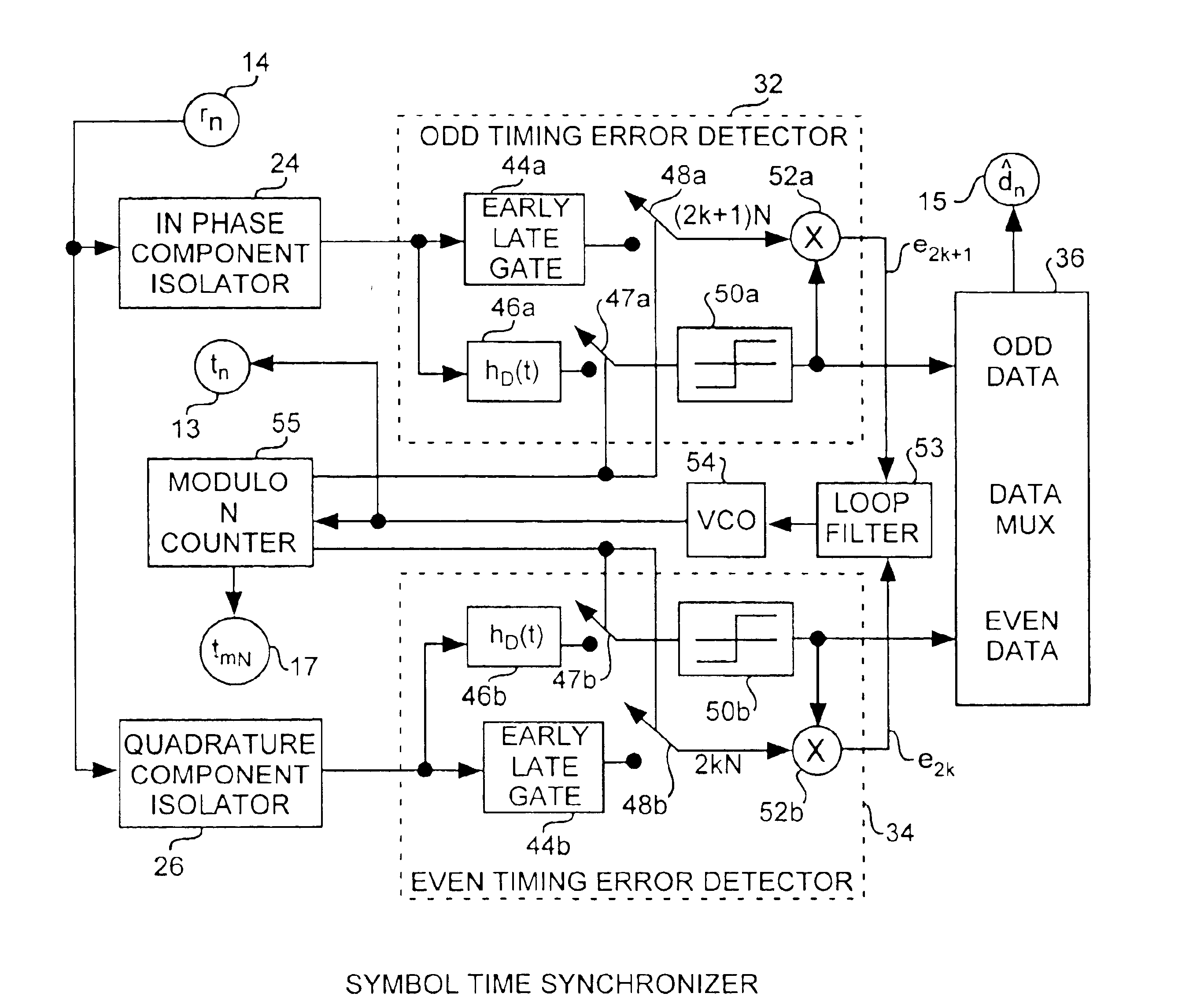
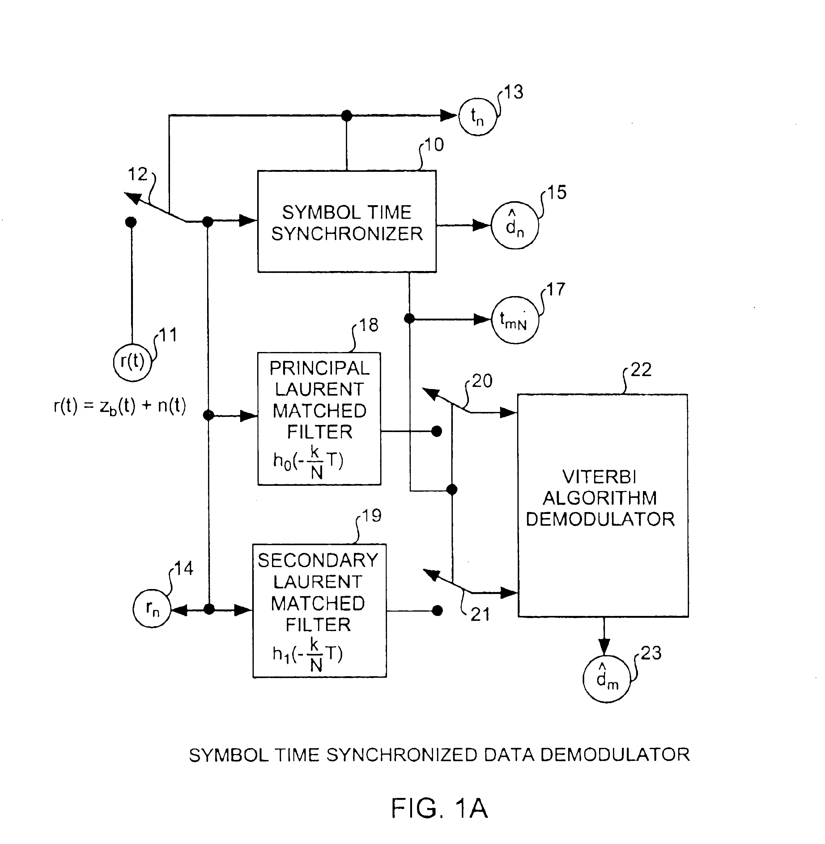
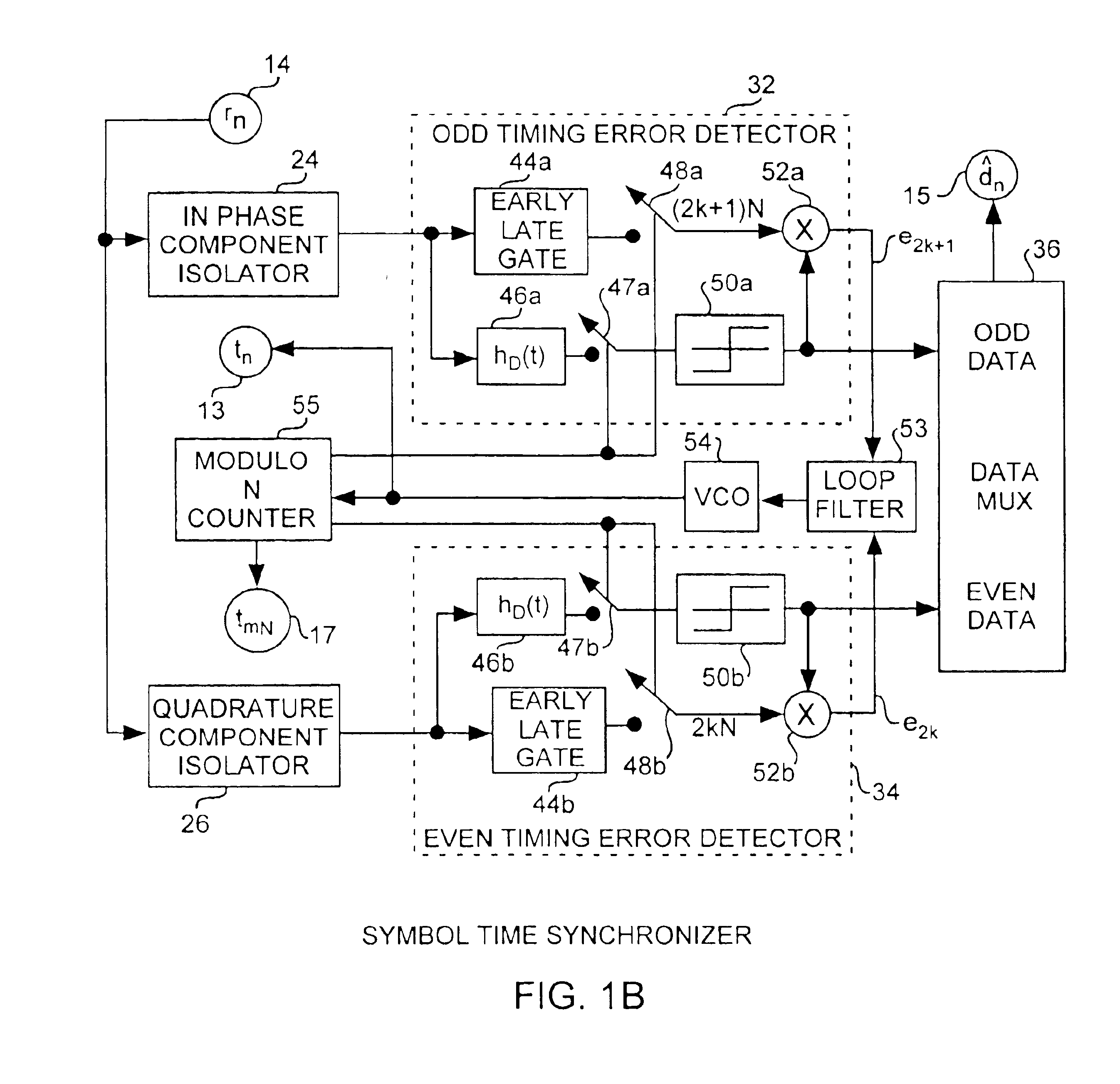
An embodiment of the invention is described with reference to the figures using reference designations as shown in the figures. Referring to FIG. 1A, a symbol time synchronized data demodulator includes a symbol time synchronizer 10 for data demodulating an r(t) received signal 11 sampled by input sampler 12 using a generated tn timing signal 13. The r(t) received signal 11 is a combination of the transmitted signal zb(t) and noise n(t) and is converted into an rn sampled input signal 14. The synchronizer 10 receives the sampled input signal 14 and provides a {circumflex over (d)}n estimate 15 of the received data sequence of the rn sampled input 14 as well as generating a tmN timing signal 17 and tn timing signal 13. The rn sampled input 14 can be communicated to conventional Laurent matched filters such as a principal Laurent matched filter 18 and a secondary Laurent matched filter 19 having respective principal and secondary matched filter outputs respectively sampled by samplers...


PUM


Abstract

Data aided carrier phase and symbol timing synchronizers are implemented at baseband as digital modulators isolating input signal inphase and quadrature component signals fed into inphase and quadrature Laurent transforms that function as data detector to provide odd and even data bit multiplexed output data signal while cross coupling the inphase and quadrature transformed outputs for removing data modulation in error signals to correct phase errors and timing errors in the received signal so as to provide reliable data demodulation of noisy received signals having dynamic carrier phase and symbol timing errors as found in continuous phase modulation communications systems such as Gaussian minimum shift keying communications systems.

Description

FIELD OF THE INVENTIONThe invention relates to the field of continuous phase modulation communications systems. More particularly, the present invention relates to symbol time tracking for continues phase modulations communications systems, such as Gaussian minimum shift keying communications systems having small bandwidth time products.BACKGROUND OF THE INVENTIONIn synchronous digital data communication systems, the carrier phase and symbol timing of the received signal must be acquired and tracked by the receiver in order to respectively demodulate the received signal and to recover the transmitted data from the received signal. Typically, receivers require carrier phase tracking for signal demodulation and symbol time tracking for data detection for generating received data streams.Continuous phase modulation (CPM) provides a class of digital phase modulation signals that have a constant envelope. The spectral occupancy of a CPM signal can be controlled or tailored to the availab...

Claims


Application Information

Patent Timeline
Patent Type & Authority Patents(United States)
IPC IPC(8): H04L27/22H04L27/14H04L27/00H04L27/20H04L27/26
CPCH04L27/2017H04L27/2662H04L27/2627H04L27/2657H04L2027/003H04L2027/0053H04L2027/0067H04L2027/0057
Inventor LUI, GEE L.TSAI, KUANG
Owner THE AEROSPACE CORPORATION
Learn More