Spring, mainspring, hairspring, and driving mechanism and timepiece based thereon

a technology of driving mechanism and mainspring, which is applied in the direction of dynamo-electric converter control, horology, instruments, etc., can solve the problem of reducing the durability of the mainspring, the inability to downsize the driving mechanism including the mainspring, and the accuracy shift of the timepiece using this signal as a reference signal

Inactive Publication Date: 2005-03-08
SEIKO EPSON CORP
View PDF30 Cites 26 Cited by
  • Summary
  • Abstract
  • Description
  • Claims
  • Application Information

AI Technical Summary

Problems solved by technology

1. The spring fixing a crystal oscillator in a wielded state poses a problem in that the wielding force of the spring causes a shift in the pace of the crystal oscillator. More specifically, dispersion of the spring wielding force causes a gain or a loss of the period of a 32 kHz signal issued by the crystal, and this leads to a problem of a shift of accuracy of a timepiece using this signal as a reference signal. The smallest possible dispersion of wielding force is therefore required for a spring fixing the crystal oscillator.
2. In a hairspring wielding a timed annular balance forming a governor for a mechanical timepiece, a temperature change results in a change in Young's modulus which in turn causes dispersion of the wielding force, and hence a change in the oscillating period of the timed annular balance. This change in the oscillating period of the timed annular balance exerts an important effect on the accuracy of a mechanical timepiece. It is therefore desirable to adopt a hairspring material, of which Young's modulus does not change under the effect of a change in temperature.
3. Further, in the case of a mainspring serving as a power source for a driving mechanism of a timepiece or the like, a mainspring satisfying contradictory requirements of a long-time operation of the driving mechanism and downsizing of the driving mechanism is demanded. More specifically, for example, a driving mechanism of a timepiece comprises a mainspring serving as a power source, a barrel drum housing the mainspring, and a train wheel transmitting a mechanical energy of the mainspring by engaging with the barrel drum. Hands of the timepiece are rotated, via a transmitting unit such as the train wheel, by the use of the rotation force produced by the release of the tightly wound mainspring.
When adopting a mainspring operable for a long period of time, therefore, it is necessary to use a larger-sized barrel drum and a larger housing space, thus leading to a problem of impossibility to downsize the driving mechanism including the mainspring.
This contrivance was however limited in terms of mainspring durability since it was difficult to maintain toughness of the mainspring.

Method used


Image

  • Spring, mainspring, hairspring, and driving mechanism and timepiece based thereon
  • Spring, mainspring, hairspring, and driving mechanism and timepiece based thereon
  • Spring, mainspring, hairspring, and driving mechanism and timepiece based thereon

Examples


first embodiment

A first embodiment relates to a driving mechanism using the spring of the invention as a mainspring. FIG. 5 is a plan view illustrating a driving mechanism of a electronically controlled mechanical timepiece using the amorphous mainspring of the invention; and FIGS. 6 and 7 are sectional views thereof.

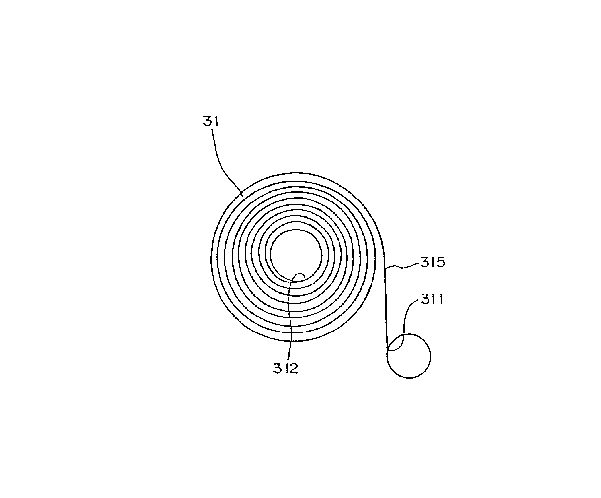
The driving mechanism 1 of the electronically controlled mechanical timepiece is provided with a barrel drum 30 having an amorphous mainspring 31, a barrel gear 32, a barrel arbor 33 and a barrel cover 34. The amorphous mainspring 31 has an outer end connected to the barrel gear 32 and an inner end fixed to the barrel arbor 33. The barrel arbor 33 is supported by a main plate 2 and a train wheel bridge 3, and secured by a ratchet wheel screw 5 to as to rotate integrally with a ratchet wheel 4.

The ratchet wheel 4 engages with a click 6 so as to rotate clockwise but not counterclockwise. Because the method of winding the amorphous mainspring 31 by rotating the ratchet wheel 4 clockwise i...

second embodiment

A driving mechanism using the amorphous mainspring of the invention will now be described. For the same or similar components as those already explained, description will be omitted or simplified hereafter.

In the driving mechanism 1 of the aforementioned first embodiment, only one amorphous mainspring 31 housed in the barrel drum 30 has served as the power source for operating the driving mechanism 1.

The driving mechanism 101 of the second embodiment differs from that of the first embodiment, as shown in FIG. 11, in that the driving mechanism 101 has two barrel drums, and amorphous mainsprings 31 housed therein serve as power sources for the driving mechanism 101.

Barrel gears 32 (not shown in FIG. 11) formed on the outer peripheries of two barrel drums 30 simultaneously engage with a base gear 71 of a center wheel 7 of the driving mechanism 101.

The two barrel drums 30 rotate in the same direction around respective barrel arbors 33, and a torque 2T comprising the sum of values of out...


PUM


Abstract

A mainspring used as a power source for a driving mechanism is made of an amorphous metal sheet, and has an S-shaped free-exploded shape. The curvature changing point, where the curving direction of the free-exploded shape changes is formed on the inner end side of a middle point between the inner end on the winding side and the outer end serving as the other end of the inner end. Because of the high tensile stress and a low Young's modulus, the amorphous metal permits increase in mechanical energy stored in the mainspring.

Description

TECHNICAL FIELDThe present invention relates to a spring used in a precision machine such as a timepiece, applicable, for example, as wielding means for fixing a crystal oscillator composing a timepiece or the like, or as a power source for a driving mechanism of a timepiece, a music box or the like.BACKGROUND ARTVarious springs have conventionally been adopted in precision machines such as a timepiece and a music box. In a timepiece, for example, there are known a spring fixing a crystal oscillator of a crystal oscillating timepiece in a wielded state, a mainspring composing a power source for a driving mechanism of a timepiece, a click spring provided for preventing back-winding upon winding a mainspring, and a hairspring wielding a timed annular balance in a mechanical timepiece.Conventional materials applicable for these springs include spring materials and mainspring materials such as carbon steel, stainless steel, a cobalt alloy, and a copper alloy. These materials have howeve...

Claims


Application Information

Patent Timeline
Patent Type & Authority Patents(United States)
IPC IPC(8): G04C3/00G04C3/14H02P8/02F16F1/10G04B1/14G04B17/06
CPCF16F1/10G04B1/145H02P8/02G04C3/14G04C3/143G04B17/066
Inventor MOTEKI, MASATOSHITAKAGI, FUMIOHARA, TATSUO
Owner SEIKO EPSON CORP
Why Eureka
Try Eureka