Eureka AIR delivers breakthrough ideas for toughest innovation challenges, trusted by R&D personnel around the world.

Fluorescent thin film, its fabrication process, and EL panel

Inactive Publication Date: 2005-03-08
IFIRE IP CORP
View PDF9 Cites 1 Cited by
  • Summary
  • Abstract
  • Description
  • Claims
  • Application Information

AI Technical Summary

Benefits of technology

Another object of the present invention is to simplify a full-color EL panel production process, thereby providing a fluorescent thin film which is less susceptible to luminance variations and can be produced in improved yields and so at lower costs and its fabrication process as well as an EL panel.

Problems solved by technology

At present, however, they are thought of as being unsuitable for color display purposes, because the properties of an EL fluorescent material for emitting the three primary colors or red, green and blue are less than satisfactory.
These fluorescent materials for emitting the three primary colors, viz., red, green and blue have problems in conjunction with light emission luminance, efficiency, color purity, etc., and so color EL panels are still on impractical levels.
However, such luminance is still unsatisfactory for blue applied to full-color displays, with chromaticity shifted to a green side.
These thiogallate fluorescent materials offer no problem in connection with color purity, but have a low luminance problem.
In particular, it is very difficult to obtain uniform thin films because such materials have a multiple composition.
Poor crystallizability due to poor composition controllability, defects due to sulfur release, contamination with impurities, etc. appear to be leading factors for a failure in obtaining thin films of high quality, and so resulting in no luminance increase.
Thioaluminate in particular has great difficulty in composition controllability.
With this process, however, it is very difficult to control the respective sources for the metals of a matrix material (SrIn2S4) and a light emission center material (Eu), thereby gaining precise control of the amount of the light emission center.
From this, too, it is found that much difficulty is experienced in control of the concentration of Eu to a precision of 5% or less.
For instance, with a film formation process capable of obtaining high luminance with one single material, it is impossible to increase the luminance of a fluorescent thin film of other color.
As a result, the fabrication process increases in complexity, with an increasing panel fabrication cost.
The use of such filters does not only make the fabrication process much more complicated, but also offer the gravest problem, viz., luminance drops.
Extraction of RGB using filters causes practically unacceptable losses of 10 to 50% of the luminance of the blue, green and red EL fluorescent thin films.

Method used


Image

  • Fluorescent thin film, its fabrication process, and EL panel
  • Fluorescent thin film, its fabrication process, and EL panel
  • Fluorescent thin film, its fabrication process, and EL panel

Examples


example 1

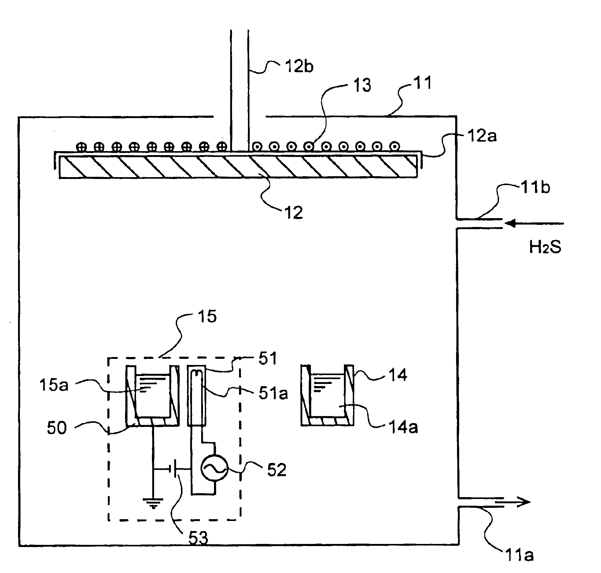
One example of the evaporation system which may be used for the fabrication process of the present invention is shown in FIG. 1. Here two electron guns were used instead of the K-cell.

An EB source 15 having Al2S3 powders charged therein with 5 mol % of Eu added thereto and an EB source 14 having metal La charged therein were placed in a vacuum chamber 11. The Al2S3 powders and metal La were simultaneously evaporated from the respective sources, and heated to 400° C. to form a film form of LaAl2S4:Eu layer on a rotating substrate. The rate of evaporation from each evaporation source was controlled in such a way that the rate of deposition of LaAl2S4 was 1 nm / sec., and the molar ratio of La:Al2S3 was 1:1. In this example, H2S gas was introduced at 20 SCCM into the evaporation system. The thus obtained thin film was then annealed at 900° C. in vacuum for 10 minutes.

By fluorescent X-ray composition analysis, the LaAl2S4:Eu thin film was found to comprise, in atomic ratio, La:Al:S:Eu=12....

example 2

Example 1 was repeated with the exception that Nd was used instead of the rare earth metal La and Ga2S3 was used in place of Al2S3. Substantially similar results were obtained. In this example, green light was emitted.

example 3

Example 1 was repeated with the exception that Y was used instead of the rare earth metal La and In2S3 was used in place of Al2S3. Substantially similar results were obtained. In this example, red light was emitted.


PUM

PropertyMeasurementUnit
Fluorescenceaaaaaaaaaa

Abstract

A fluorescent thin film is provided, including a matrix material containing as a main component a rare earth sulfide or a rare earth selenide and a rare earth element additive as a light emission center. The rare earth element additive is different from the rare earth element used for the matrix material.

Description

BACKGROUND OF THE INVENTIONThe present invention relates generally to a sulfide light-emitting layer used for inorganic EL devices, and more particularly to a fluorescent thin film used for a light-emitting layer and an EL panel using the same.In recent years, thin-film EL devices used for small- or large-format yet lightweight flat displays have been under extensive studies. A monochromatic thin-film EL display using a fluorescent thin film comprising manganese-added zinc sulfide for emitting yellowish orange light has already been put to practical use in the form of a double-insulation type structure using such thin-film insulating layers 2 and 4 as shown in FIG. 2. Referring here to FIG. 2, a lower electrode 5 is formed on a substrate 1 in a predetermined pattern, and a first insulating layer 2 is formed on the lower electrode 5. The first insulating layer 2 is provided thereon with a light-emitting layer 3 and a second insulating layer 4 in this order, and the second insulating ...

Claims


Application Information

Patent Timeline
IPC IPC(8): C09K11/88C09K11/77H05B33/14H05B33/10C09K11/00C09K11/08C09K11/80C09K11/84
CPCC09K11/7767C09K11/7774C09K11/7784C09K11/886H05B33/14C09K11/7792Y10S428/917C09K11/77
Inventor YANO, YOSHIHIKO
Owner IFIRE IP CORP
Why Eureka
Eureka Blog
Learn More