Backlight inverter for liquid crystal display panel of asynchronous pulse width modulation driving type

Inactive Publication Date: 2005-03-08
SAMSUNG ELECTRO MECHANICS CO LTD
View PDF4 Cites 33 Cited by
  • Summary
  • Abstract
  • Description
  • Claims
  • Application Information

AI Technical Summary

Benefits of technology

Therefore, the present invention has been made in view of the above problems, and it is an object of the present invention to provide a backlight inverter for an LCD panel of an asynchronous PWM driving type, which is capable of delaying a plurality of pairs of PWM drive signals, which are inputted respectively to power switches to drive a plurality of CCFLs in pairs, sequentially by a predetermined time

Problems solved by technology

However, the aforementioned conventional backlight inverter for the LCD panel has a disadvantage in that a plurality of used lamps are synchronized to have the same PWM on/off periods, resulting in the occurrence of overshoot in a power supply

Method used


Image

  • Backlight inverter for liquid crystal display panel of asynchronous pulse width modulation driving type
  • Backlight inverter for liquid crystal display panel of asynchronous pulse width modulation driving type
  • Backlight inverter for liquid crystal display panel of asynchronous pulse width modulation driving type

Examples


Embodiment Construction

Now, preferred embodiments of the present invention will be described in detail with reference to the annexed drawings. In the drawings, the same or similar elements are denoted by the same reference numerals even though they are depicted in different drawings.

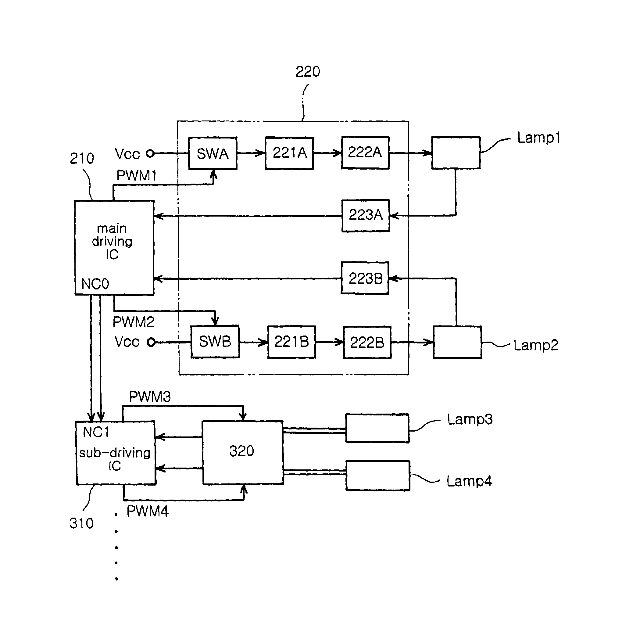
FIG. 4 is a block diagram showing the construction of a backlight inverter for an LCD panel in accordance with the present invention, FIG. 5 is a circuit diagram of a main driving IC and an associated lamp operating circuit in FIG. 4, and FIG. 6 is a circuit diagram of a sub-driving IC and an associated lamp operating circuit in FIG. 4.

With reference to FIGS. 4 to 6, the backlight inverter for the LCD panel according to the present invention is adapted to drive a plurality of lamps Lamp1-Lamp4 in pairs. To this end, the backlight inverter comprises a main driving IC 210 for generating PWM pulses P11 and P12 in response to a dimming voltage Vdim based on a brightness control and an internally generated PWM oscillation signal PW...


PUM


Abstract

A backlight inverter for an LCD panel of an asynchronous pulse width modulation (PWM) driving type which is capable of driving a plurality of cold cathode fluorescent lamps (CCFLs) in pairs and controlling a plurality of PWM drive signals for respective operations of the lamps to make the phases thereof different. The backlight inverter comprises a main driving integrated circuit (IC), at least one sub-driving IC, and a plurality of lamp operating circuits for operating the pairs of lamps in response to the first and second PWM drive signals and the third and fourth PWM drive signals, respectively. The lamps have different PWM on/off periods so that overshoot of a power supply circuit can be reduced so as to keep the entire system power stable.

Description

BACKGROUND OF THE INVENTION1. Field of the InventionThe present invention relates to a backlight inverter for a thin film transistor-liquid crystal display (TFT-LCD) panel, and more particularly to a backlight inverter for an LCD panel of an asynchronous pulse width modulation (PWM) driving type, which is capable of delaying a plurality of pairs of PWM drive signals, which are inputted respectively to power switches to drive a plurality of cold cathode fluorescent lamps (CCFLs) in pairs, sequentially by a predetermined time interval in such a manner that the PWM drive signal pairs corresponding respectively to the lamp pairs have different phases and the lamps thus have different PWM on / off periods, so that overshoot of a power supply circuit can be reduced so as to keep the entire system power stable and so that switching noise based on PWM dimming can be reduced so as to reduce screen noise and increase system reliability.2. Description of the Related ArtGenerally, CCFLs are opera...

Claims


Application Information

Patent Timeline
IPC IPC(8): H05B41/39H05B41/282H05B41/28H05B41/392H02M7/493H05B41/24
CPCH05B41/2824H05B41/3927Y02B20/186Y02B20/00H05B41/24
Inventor MIN, BYOUNG OWNJEON, HYOUNG JUNKIM, HYUN JIN
Owner SAMSUNG ELECTRO MECHANICS CO LTD
Why Eureka
Try Eureka