Switching power supply device

a power supply device and switching power technology, applied in the direction of electric variable regulation, process and machine control, instruments, etc., can solve the problems of increasing power loss, achieve the effect of reducing the noise radiated to the outside reducing the size and reducing the noise of the switching power supply devi

Active Publication Date: 2011-01-27
COSEL
View PDF5 Cites 16 Cited by
  • Summary
  • Abstract
  • Description
  • Claims
  • Application Information

AI Technical Summary

Benefits of technology

[0032]According to a switching power supply device of this invention, a recovery current generated in a diode which is connected in parallel to a conventional synchronized rectifying element can be restrained by adding an auxiliary rectification circuit of a simple configuration, so that a power loss due to the recovery operation hardly occurs. Therefore, this device can contribute to high efficiency and miniaturization of the switching power supply device.
[0033]In addition, the generation of a surge voltage due to a recovery current is also restrained simultaneously, and further, the energy accumulated in a leakage inductance such as a transformer or a smoothing inductor can also be absorbed by an auxiliary rectification circuit, so that: switching noise radiated to the outside of the switching power supply device can be reduced; and a filter circuit or the like for noise troubleshooting can be reduced.
[0034]Further, in the auxiliary rectification circuit, a time constant switching circuit, which switches a time constant of a current path including an auxiliary capacitor in accordance with an orientation of a current, is added, so that a current stress applied to a main oscillation element or the like can be alleviated, reliably preventing a recovery operation of a diode which is connected in parallel to a synchronized rectifying element.
[0035]Furthermore, drive control of an auxiliary switch element is facilitated by connecting an auxiliary diode in parallel to each end of an auxiliary switch element, so that a configuration of a circuit part related to drive of an auxiliary switch element inside a control circuit can be simplified.
[0036]Still furthermore, a delay time from turning-off of a synchronized rectifying element to turning-on of a main oscillation element is the one set within a time interval taken until a voltage across the main oscillation element lowers to zero volt, whereby: a loss of the main oscillation element can be reduced; and the generation of switching noise due to the main oscillation element can be restrained.MODES FOR CARRYING OUT THE INVENTION
[0037]Hereinafter, a switching power supply device 20 of a first embodiment of this invention will be described with reference to FIGS. 1 to 3. Like constituent elements of the abovementioned switching power supply device 10 are designated by like reference numerals, each of which is explained.

Problems solved by technology

However, the abovementioned switching power supply device 10 has entailed a problem that, in the duration IV, a power loss increases due to the recovery current flowing into the PN-junction-type parasitic diode DSR1.

Method used


Image

  • Switching power supply device
  • Switching power supply device
  • Switching power supply device

Examples


first embodiment

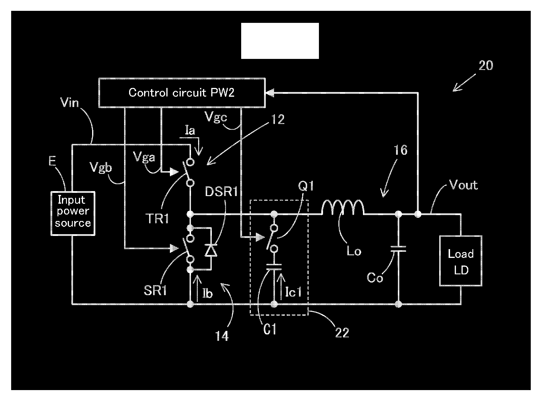
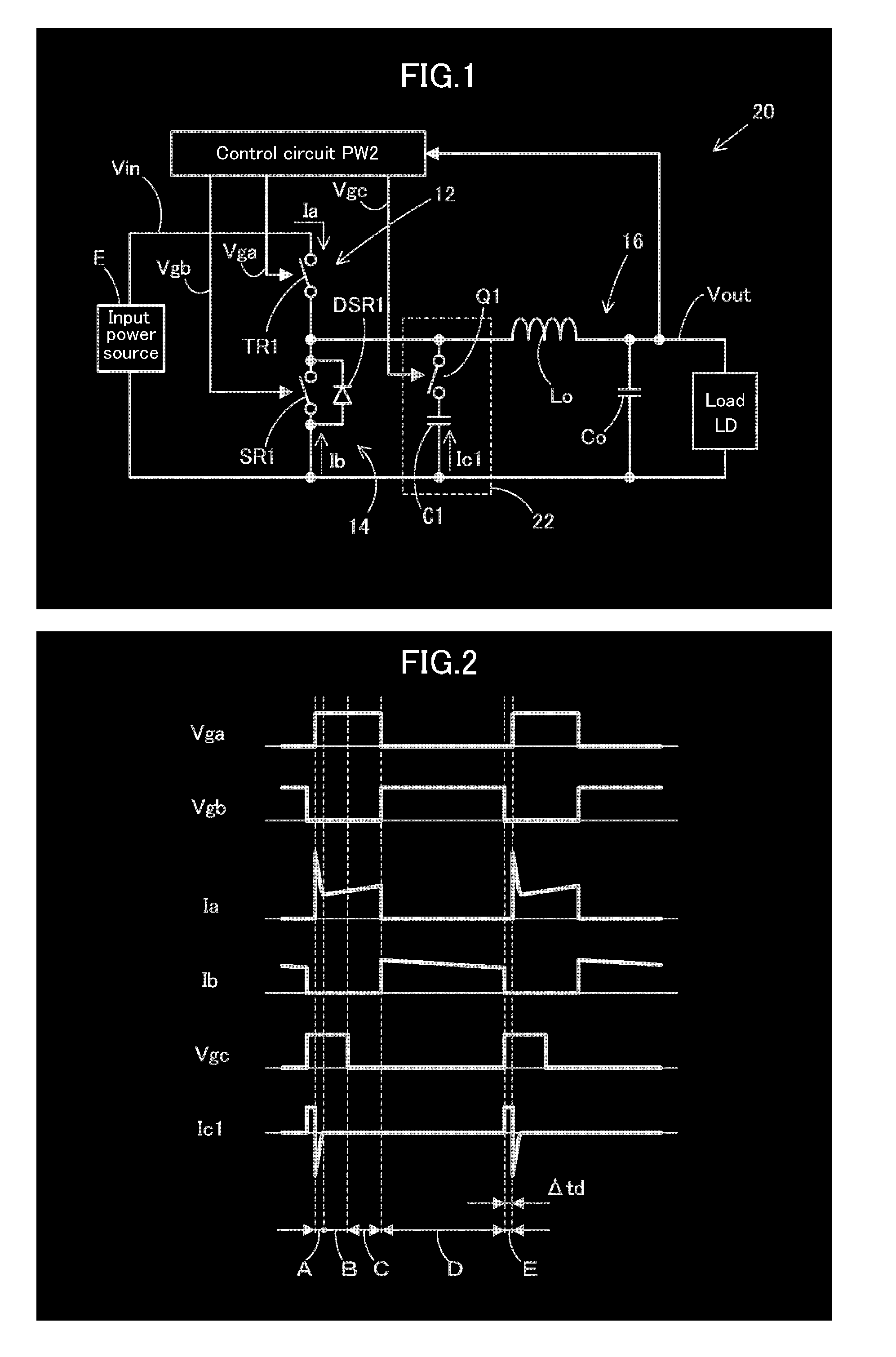
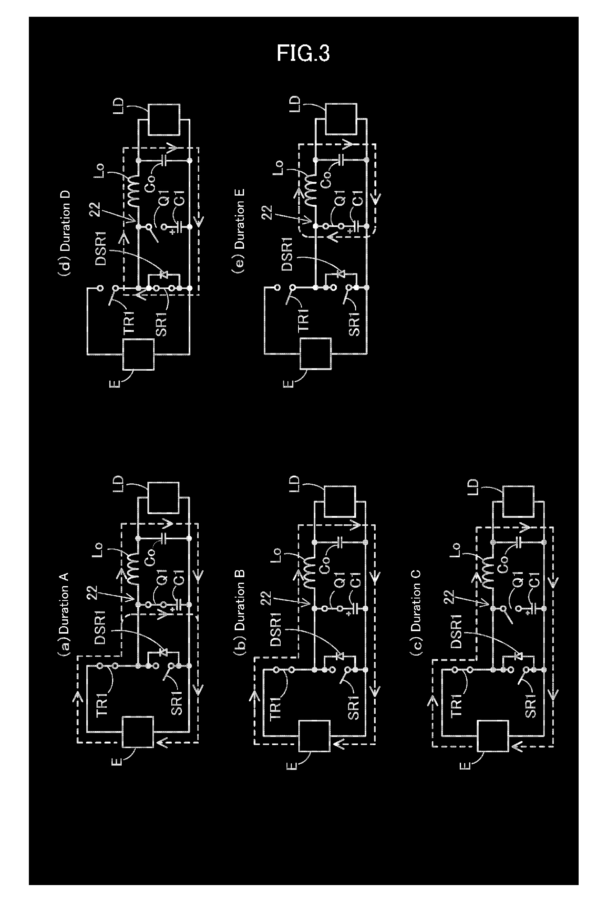
[0037]Hereinafter, a switching power supply device 20 of this invention will be described with reference to FIGS. 1 to 3. Like constituent elements of the abovementioned switching power supply device 10 are designated by like reference numerals, each of which is explained.

[0038]The switching power supply device 20, as shown in FIG. 1, is comprised of: a step-down chopper system similar to the one of the switching power supply device 10; and comprises an inverter circuit 12 having a main oscillation element TR1, one terminal of which is connected to a positive side of an input power source E for supplying an input voltage Vin, allowing a predetermined intermittent voltage to be generated at the other terminal of the main oscillation element TR1 by turning on / off the main oscillation element TR1. The main oscillation element TR1 is an Nch-FET, for example, a drain terminal is connected to the positive side of the input power source E, and a source terminal serves as an output of an in...

second embodiment

[0050]Next, a switching power supply device 30 of this invention will be described with reference to FIGS. 4 to 6. Like constituent elements of the abovementioned switching power supply device 20 are designated by like reference numerals, and a duplicate description thereof is omitted. The switching power supply device 30, as shown in FIG. 4, is configured in such a manner that is substantially similar to that of the switching power supply device 20, but is different therefrom in that an auxiliary rectification circuit 32 is provided in place of the auxiliary rectification circuit 22.

[0051]The auxiliary rectification circuit 32 has a configuration in which a time constant switching circuit 34 has been serially inserted into the auxiliary capacitor C1 of the auxiliary rectification circuit 22 described above. The time constant switching circuit 34 is comprised of: a serial circuit of a resistor R1 and a diode D1; and a resistor R2 which is connected to the serial circuit in parallel,...

third embodiment

[0058]Next, a switching power supply device 40 of this invention will be described with reference to FIGS. 7 and 8. Here, like constituent elements of the abovementioned switching power supply device 30 are designated by like reference numerals, and a duplicate description thereof is omitted. The switching power supply device 40, as shown in FIG. 7, is configured in such a manner that is substantially similar to that of the switching power supply device 30, and is different therefrom in that an auxiliary rectification circuit 42 is provided in place of the auxiliary rectification circuit 32.

[0059]The auxiliary rectification circuit 42 comprises a serial circuit of an auxiliary switch element Q1, a time constant switching circuit 34, and an auxiliary capacitor C1, and further, an auxiliary diode DQ1 is connected in parallel to each end of the auxiliary switch element Q1 in an orientation in which a current can be flown from the main oscillation element TR1 toward the auxiliary capaci...


PUM


Abstract

Provided is a switching power supply device that can limit the generation of recovery current of diodes connected in parallel between the two ends of a synchronized rectifying element by the addition of a simple circuit, and that improves efficiency and facilitates miniaturization. The device comprises a synchronized rectifying element (SR1) that turns on and off complementarily with a main oscillation element (TR1) that is connected in series with an input power supply (E), and a parasitic diode (DSR1) that is connected to the two ends of the synchronized rectifying element (SR1) in a direction enabling current supply toward a smoothing circuit (16). The device is equipped with a control circuit (PW2) that generates a control pulse with which is set the time delay for turning on the oscillation element (TR1) after a certain period of time after the synchronized rectifying element (SR1) is turned off has elapsed, and that drives the main oscillation element (TR1) and the synchronized rectifying element (SR1) based on the control pulse. An auxiliary rectification circuit (22) comprising a series circuit formed by an auxiliary switch element (Q1) and an auxiliary capacitor (C1) driven by the control circuit (PW2) is provided between the two ends of the parasitic diode (DSR1).

Description

TECHNICAL FIELD[0001]This invention relates to a switching power supply device for converting an input voltage to a desired direct current voltage and supply power to electronic equipment, and in particular, to a switching power supply device provided with a synchronized rectifying element which turns on / off complementarily with a main oscillation element.BACKGROUND ART[0002]Conventionally, a switching power supply device 10 of a step-down chopper system, shown in FIG. 16, for example, is known as a switching power supply device provided with: a main oscillation element which is connected to an input power source in series; and a synchronized rectifying element which turns on / off complementarily with the main oscillation element.[0003]First, a circuit configuration of the switching power supply device 10 will be described. This power supply device is provided with an inverter circuit 12 having a main oscillation element TR1, one terminal of which is connected to a positive side of a...

Claims


Application Information

Patent Timeline
Patent Type & Authority Applications(United States)
IPC IPC(8): G05F1/10
CPCH02M3/158Y02B70/1466H02M3/1588H02M1/34H02M1/344Y02B70/10
Inventor HORII, KAZUHIRO
Owner COSEL
Why Eureka
Try Eureka