Active snubber for transition mode power converter

a technology of power converter and active snubber, which is applied in the direction of power conversion system, dc-dc conversion, instruments, etc., can solve the problems of the prior power converter b>100/b> of fig. 1 that are less desirable for higher power applications, and achieve the effect of reducing the loss of turn on switching, and increasing the converter efficiency

Active Publication Date: 2011-08-16
MYPAQ HLDG LTD
View PDF20 Cites 14 Cited by
  • Summary
  • Abstract
  • Description
  • Claims
  • Application Information

AI Technical Summary

Benefits of technology

[0005]Accordingly, the present invention provides a transition mode power converter that is well suited for a number of applications including for high power applications. The transition mode power converter includes active snubber circuitry. The active snubber may also be referred to as a switch mode snubber. The active snubber is used on the transition mode power converter to absorb the energy in the leakage inductance from the transformer, as well as any stray inductance. The active snubber will then transform the absorbed energy to the secondary side of the converter, and also use part of that energy to help the primary switch to achieve ZVS and eliminate turn on switching loss. This increases the converter efficiency and enables higher switching frequency operation. This also reduces the switching noise that is associated with the switch on and switch off, and thus reduces the EMI signature of the power converter. The present inventor has recognized that how to control the auxiliary switch that controls the on / off of the active snubber, including the right timing and right gate voltage level for the auxiliary switch, are issues of significance. The present invention addresses these issues in a simple and low cost way by controlling operation of the auxiliary switch with an auxiliary winding on the transformer.

Problems solved by technology

Considerations such as these can make the prior power converter 100 of FIG. 1 less desirable for higher power applications.

Method used


Image

  • Active snubber for transition mode power converter
  • Active snubber for transition mode power converter
  • Active snubber for transition mode power converter

Examples


Embodiment Construction

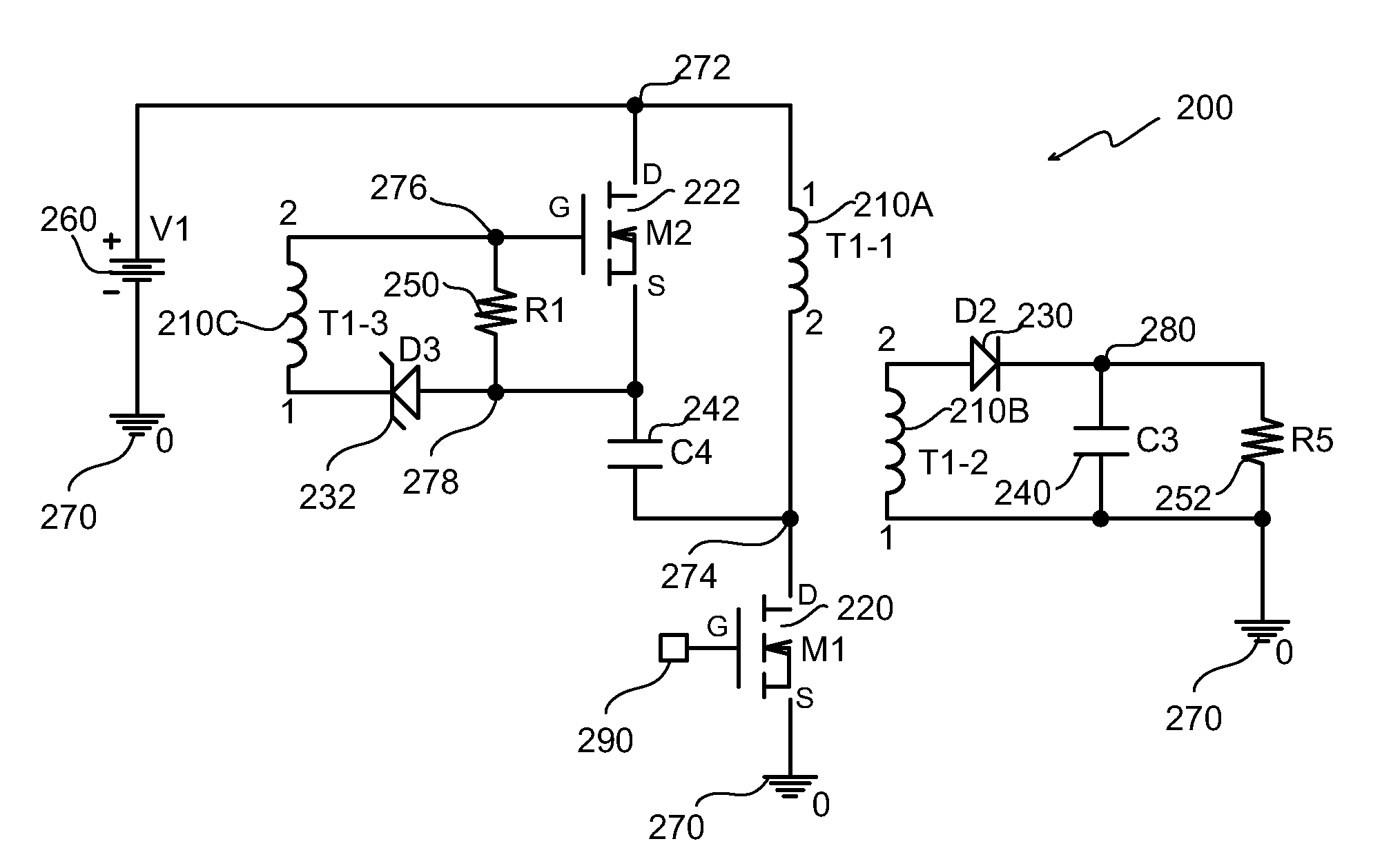
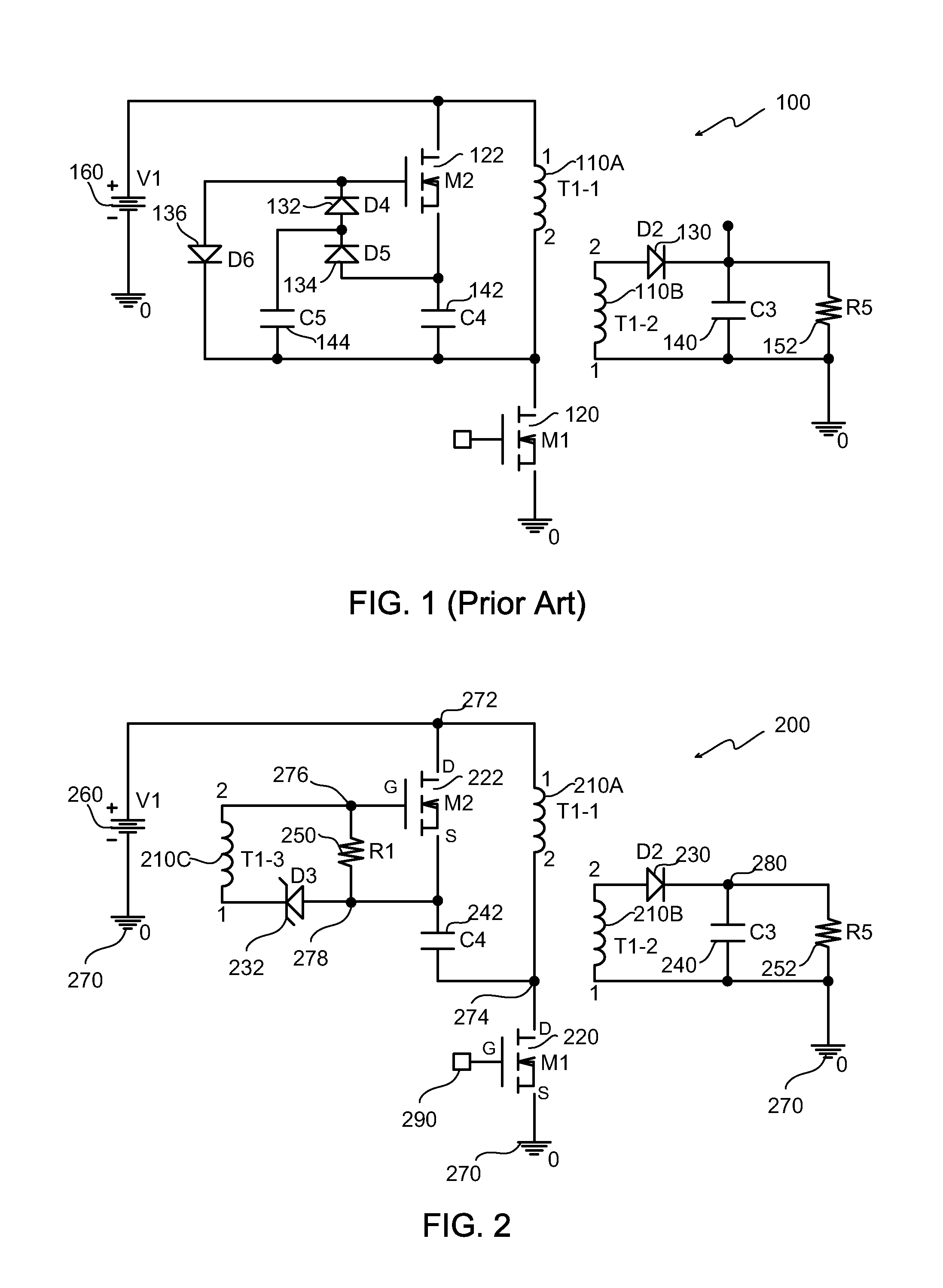
[0016]FIG. 2 is a schematic diagram showing one embodiment of a transition mode power converter 200. The power converter 200 includes a transformer (T1) 210, two MOSFETS (M1, M2) 220 and 222, a diode (D2) 230, a zener diode (D3) 232, two capacitors (C3, C4) 240 and 242, and two resistors (R1, R5) 250 and 252. The power converter 200 is shown connected to a direct current voltage source 260. The transformer 210 includes primary and secondary windings (T1-1, T1-2) 210A and 210B and an auxiliary winding (T1-3) 210C.

[0017]The MOSFETS (M1, M2) 220 and 222 may be referred to herein as the primary MOSFET (M1) 220 and the auxiliary MOSFET (M2) 222. In FIG. 2, parasitic capacitances and inherent body diode characteristics of the primary and auxiliary MOSFETS (M1, M2) 220 and 222 are not illustrated. The primary MOSFET (M1) 220 may also be referred to herein as the primary switch and the auxiliary MOSFET (M2) 222 may also be referred to herein as the auxiliary switch. In this regard, the prim...


PUM


Abstract

A transition mode power converter having an active snubber the operation of which is controlled using an auxiliary winding on the transformer of the power converter. In one embodiment, the power converter includes a transformer having a primary winding connected to a voltage source, a primary switch, an auxiliary switch, a capacitor, and an auxiliary winding on the transformer. The primary switch includes a first terminal connected to the primary winding of the transformer and a second terminal connected to a common node. The auxiliary switch includes a first terminal connected to the voltage source and to the primary winding. The capacitor is connected between a second terminal of the auxiliary switch and the first terminal of the primary switch. The auxiliary winding of the transformer is connected to a third terminal of the auxiliary switch and controls operation of the auxiliary switch via the third terminal.

Description

FIELD OF THE INVENTION[0001]The present invention relates generally to power converters, and more particularly to transition mode power converters, in some cases also referred to as critical conduction mode, or boundary mode converters.BACKGROUND OF THE INVENTION[0002]One embodiment of a prior power converter 100 that may operate in transition mode is schematically depicted in FIG. 1. In this regard, transition mode may be defined as a boundary mode between a discontinuous operating mode and continuous operating mode. The power converter 100 of FIG. 1 includes a transformer (T1) 110, two MOSFETS (M1, M2) 120 and 122, four diodes (D2, D4, D5, D6) 130-136, three capacitors (C3, C4, C5) 140-144, and a resistor (R5) 152. The power converter 100 is shown connected to a direct current voltage source 160. The transformer 110 includes primary and secondary windings (T1-1, T1-2) 110A and 110B. The MOSFETS (M1, M2) 120 and 122 may be referred to herein as the primary MOSFET (M1) 120 and the a...

Claims


Application Information

Patent Timeline
Patent Type & Authority Patents(United States)
IPC IPC(8): H02M3/335
CPCH02M1/34H02M3/335H02M2001/344H02M1/344
Inventor ZHANG, XIAOYANG
Owner MYPAQ HLDG LTD
Why Eureka
Try Eureka