
Method and device for controlling an electric load connected to a multiphase switchable DC/AC frequency convertor

a multi-phase switchable, electric load technology, applied in the direction of ac-dc conversion, electric variable regulation, instruments, etc., can solve the problem of reducing the speed at which the motor current can be adjusted, and achieve the effect of shortening the time period

Inactive Publication Date: 2005-03-08
ENGIE ELECTROPROJECT BV
View PDF8 Cites 9 Cited by
  • Summary
  • Abstract
  • Description
  • Claims
  • Application Information

AI Technical Summary

Benefits of technology

"The invention provides a new method for controlling the value of a quantity in an electrical load connected to a multi-phase switchable DC / AC frequency convertor. The method allows for a more efficient and faster control of the quantity compared to previous methods. It achieves this by varying the current or voltage delivered by the convertor in a way that reduces the deviation of the quantity from its desired value. The method uses a dead zone that is oriented in relation to the voltage or current delivered by the convertor, and the switches of the convertor are switched in a way that allows the quantity to be controlled within the dead zone. The method can be used with different types of frequency convertors and can control the phase angle of the quantity being realized. It also allows for optimizing the quantity to be controlled when the output of the frequency convertor reaches its limits."

Problems solved by technology

The use of a desired voltage value related to the motor current to be realized has a delaying effect on the speed at which the motor current can be adjusted, however.

Method used


Image

  • Method and device for controlling an electric load connected to a multiphase switchable DC/AC frequency convertor
  • Method and device for controlling an electric load connected to a multiphase switchable DC/AC frequency convertor
  • Method and device for controlling an electric load connected to a multiphase switchable DC/AC frequency convertor

Examples


Embodiment Construction

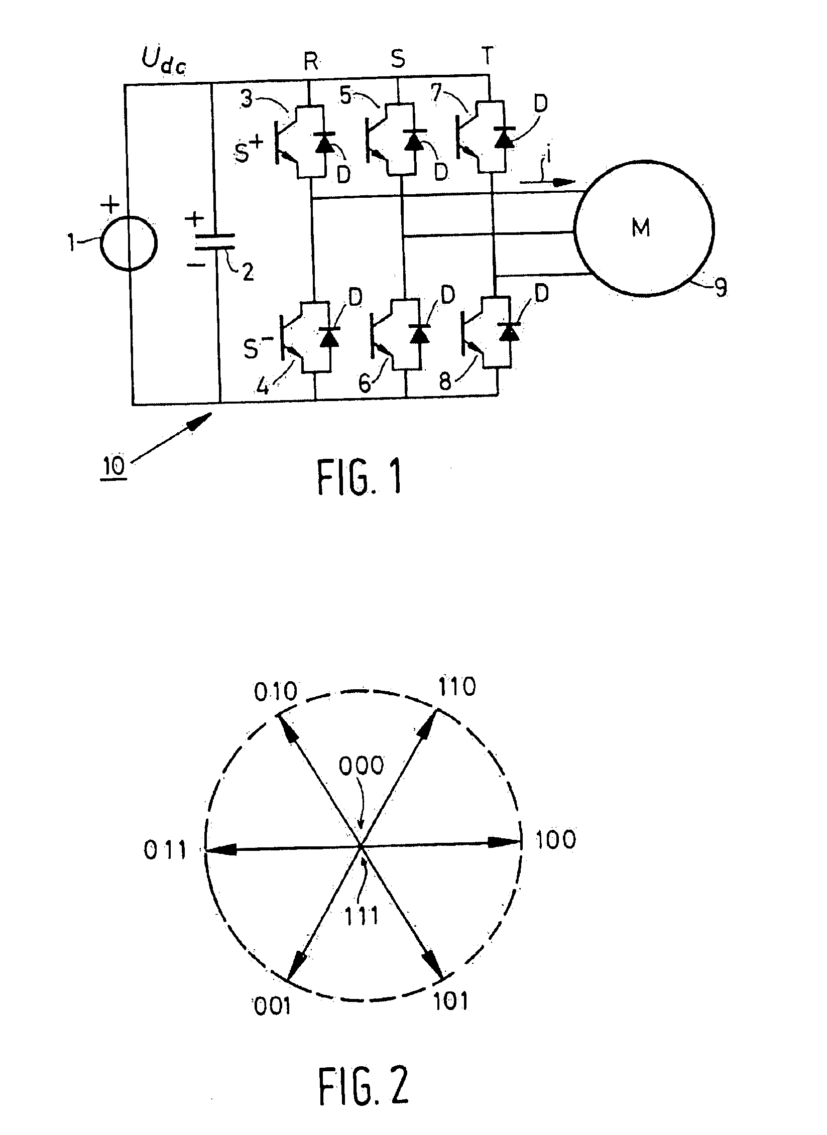
As is schematically shown in FIG. 1, a VSI 10 roughly consists of a DC source, to which two switches S+ and S− connect in series for each of the phases RST of the output voltage to be realized, these switches being indicated by the numerals 3, 5, 7, respectively, for the S+ switches and 4, 6, 8, respectively, for the S− switches.

An electrical load in the form of a three-phase AC motor 9 is connected to the centers between the respective switches 3, 4; 5, 6 and 7, 8. The switches 3-8 are connected to a DC power supply source 1, to the output terminals of which one or more capacitors 2 are connected as an interstage circuit. Only one capacitor 2 is shown by way of example in the Figure.

The switches 3-8 are IGBT- or GT0-type semiconductor switches, for example, and a diode D is connected in anti-parallel across the conducting path of each of the semiconductor switches.

Three states can be distinguished for each of the phases R, S and T:state 1: the switch S+ is on (conducting) and the s...


PUM


Abstract

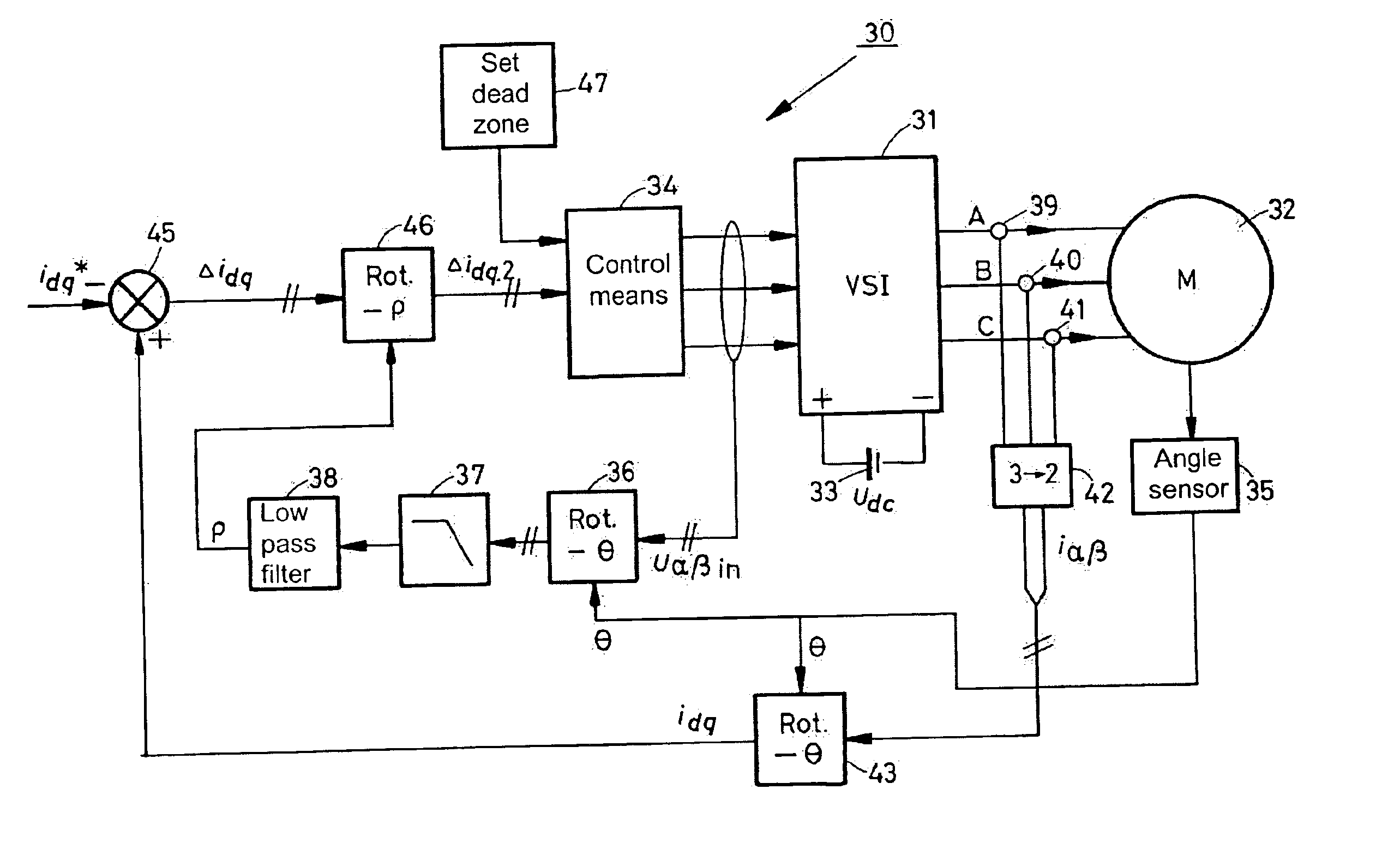
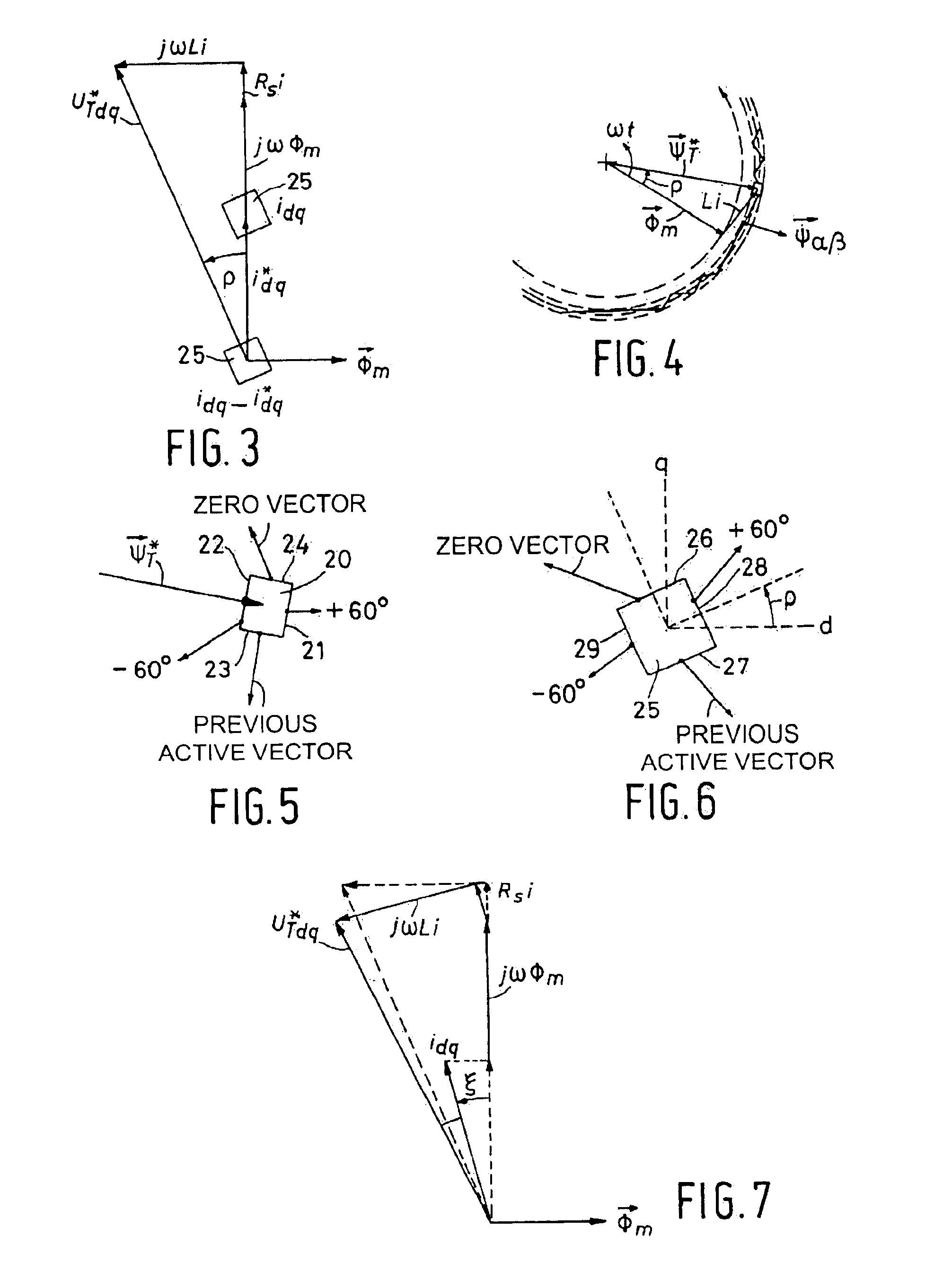
A method and a device for realizing an effective value of a quantity to be varied in an electrical load connected to a multi-phase switchable DC / AC frequency convertor comprising a plurality of controllable switches. The value is realized by varying a current or a voltage delivered by the DC / AC frequency convertor through suitable switching of the switches thereof, and wherein the quantity exhibits a load angle which, averaged in time, leads or lags the voltage or current being delivered. The method and / or the device is arranged for carrying out the steps comprising the defining of a dead zone having dimensions that are representative of an allowable amplitude and phase angle deviation in the quantity to be realized; the orienting of the dead zone with respect to the voltage or current delivered by the DC / AC frequency convertor by rotating the dead zone through the load angle in the direction of the delivered voltage or current; and the switching of one or more of the switches on the basis of the manner in which the deviation in the quantity to be realized extends beyond the dead zone, for the purpose of realizing the quantity during operation with an amplitude and phase deviation ranging within the dead zone.

Description

BACKGROUND OF THE INVENTION1. Field of the InventionThe invention relates to a method for realizing an effective value of a quantity to be varied in an electrical load connected to a multi-phase switchable DC / AC frequency convertor comprising a plurality of controllable switches.2. Description of Related ArtAn electrical load within the context of the present invention is e.g. a controllable electrical drive unit consisting of a multi-phase (usually three-phase) electric motor, whose windings are connected to the frequency convertor. The frequency convertor is fed with direct current, which direct current is converted into a controllable alternating current by suitably turning the switches of the frequency convertor on and off. Consequently, the frequency convertor converts a direct current voltage (DC) into an alternating current voltage (AC) having an adjustable amplitude and frequency. In English professional literature, such frequency convertors are also indicated by the term “i...

Claims


Application Information

Patent Timeline
Patent Type & Authority Patents(United States)
IPC IPC(8): H02M7/5387
CPCH02M7/53875H02M2007/53876H02M7/53876
Inventor VELTMAN, ANDRE
Owner ENGIE ELECTROPROJECT BV
Learn More