Variable field magnet apparatus

a variable field, magnet technology, applied in the direction of magnets, magnet bodies, cores/yokes, etc., can solve the problems of large heat generation, bulky devices, and high manufacturing cost, and achieve the effect of generating a large amount of hea

Active Publication Date: 2005-03-08
APPLIED MATERIALS INC
View PDF27 Cites 81 Cited by
  • Summary
  • Abstract
  • Description
  • Claims
  • Application Information

AI Technical Summary

Benefits of technology

By moving the first or second member which is rotatively coupled to the permanent magnets, the magnets are rotated at the same angular velocity and in the same rotational direction to modify the strength of the m

Problems solved by technology

A DC power supply negatively biases the target with respect to the shield.
Some of the problems are associated with contact and via holes in the semiconductor wafers.
Such high aspect ratios present a problem for sputtering because some forms of sputtering are not strongly anisotropic, so that the initially sputtered material preferentially deposits at the top of the hole

Method used


Image

  • Variable field magnet apparatus
  • Variable field magnet apparatus
  • Variable field magnet apparatus

Examples


Embodiment Construction

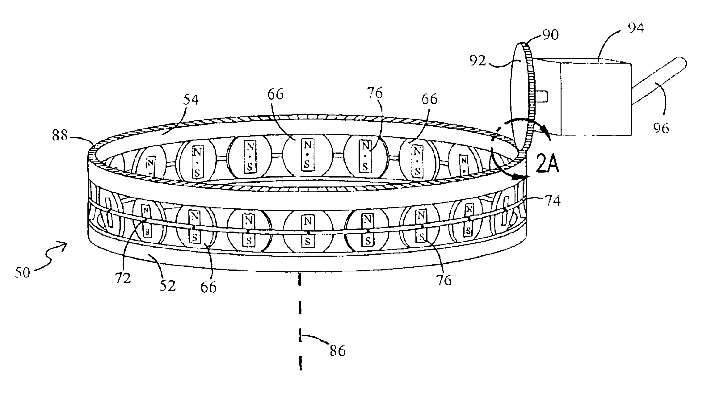
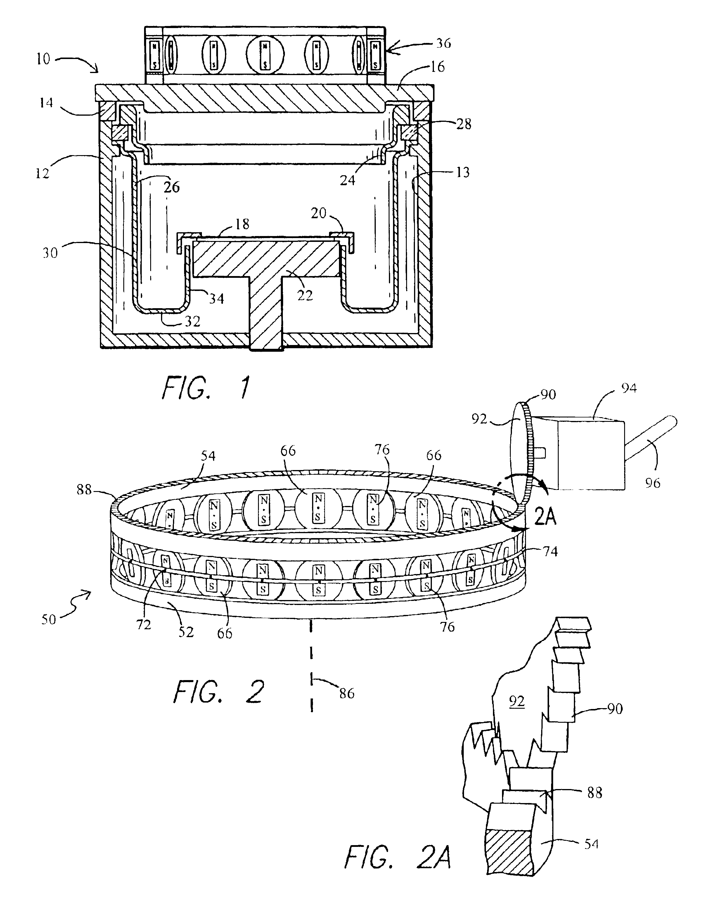
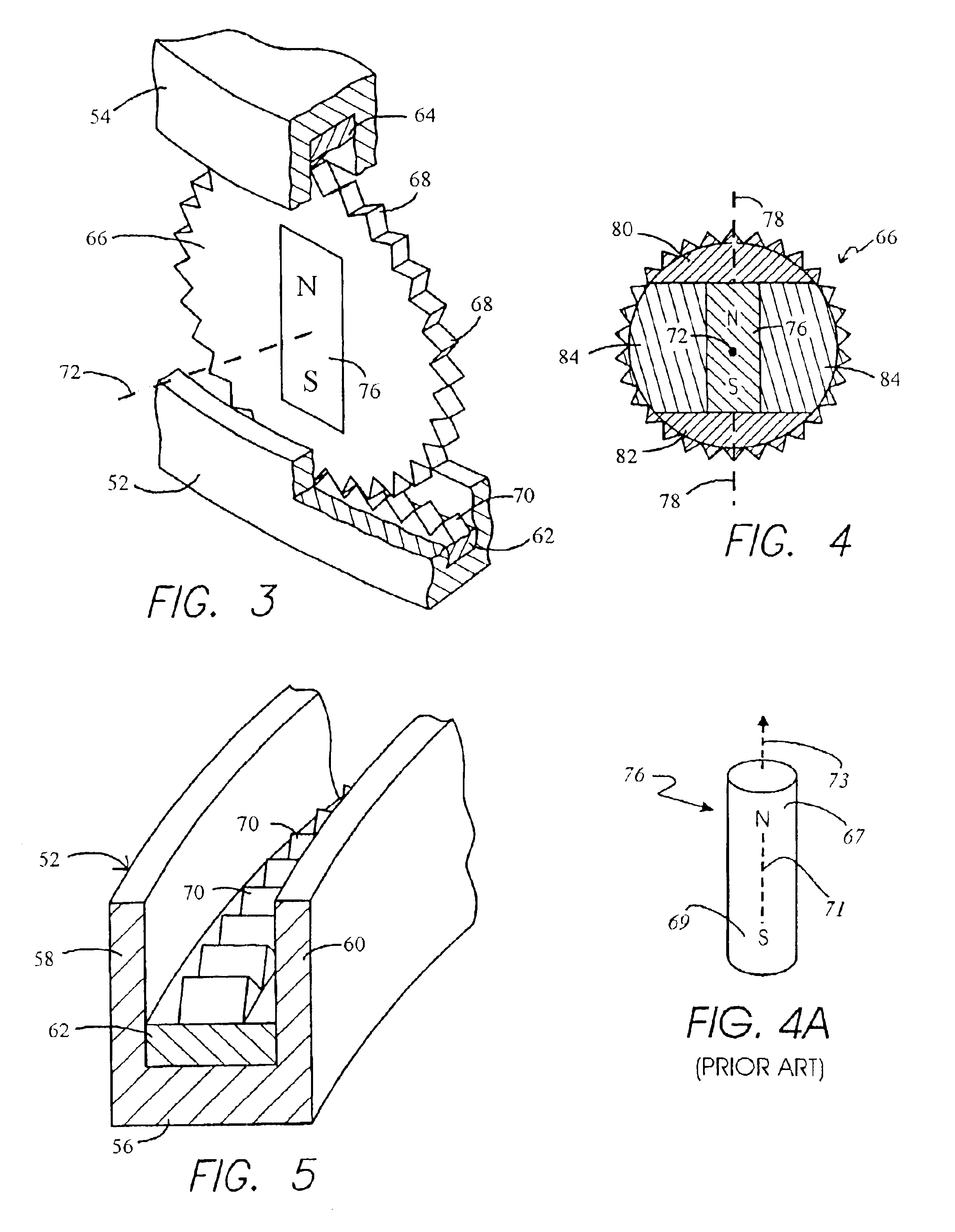
A magnet assembly for producing a varying magnetic field is provided. A plurality of permanent magnets are adapted to project magnetic fields and disposed in an array in a generally closed-loop arrangement, such as for example, a circular arrangement. Each of the magnets has a magnetic north pole and a magnetic south pole which define a magnetic polar axis.

The north pole and magnetic polar axis of each magnet in turn define a magnetic orientation of that magnet, and the magnetic orientations of all of the magnets are positioned in a common magnetic orientation. The projected magnetic fields vary as a function of the common magnetic orientation of the magnets. An orienter is mechanically coupled to the magnets and is adapted to change the common magnetic orientation of the magnets from a first to a second orientation wherein the projected magnetic fields are changed.

In one embodiment, the magnet assembly comprises first and second annular-shaped members having a center axis of rotati...


PUM

PropertyMeasurementUnit
Lengthaaaaaaaaaa
Thicknessaaaaaaaaaa
Magnetic fieldaaaaaaaaaa

Abstract

A magnet assembly for producing a varying magnetic field is provided wherein a plurality of permanent magnets are interposed between two members which are constructed of a ferromagnetic material. Each of the magnets is rotatable and has a north and south magnetic pole. Each of the magnets is disposed so that the north magnetic poles of the plurality of permanent magnets have a common magnetic orientation with respect to the first member. An orienter, such as, for example, a ring gear and pinion arrangement, is coupled to the magnets to change their common magnetic orientation with respect to the first member. The magnetic field projected by the assembly varies as a function of the orientation of the magnets.

Description

FIELD OF THE INVENTIONThis invention relates in general to the field of magnetic devices, and more particularly, to an apparatus and method for producing with permanent magnets a varying magnetic field, such as for example, a magnetic field as used in semiconductor processing.BACKGROUNDThe need for producing variable magnetic fields arises in a number of industries and fields of endeavor, especially in the manufacturing sectors. One example can be found in the semiconductor processing industry.Sputtering, alternatively called physical vapor deposition (PVD), is a widely used method of depositing layers of metals and related materials in the fabrication of semiconductor integrated circuits. A conventional PVD reactor includes a vacuum chamber sealed to a PVD target composed of the material, usually a metal, to be sputter deposited on a wafer held on a wafer support, or pedestal. A shield held within the chamber protects the chamber wall from the sputtered material and provides the an...

Claims


Application Information

Patent Timeline
IPC IPC(8): H01J37/32H01J37/34H01F7/02
CPCH01J37/3455H01J37/3405H01F7/0226
Inventor PERRIN, MARK A.
Owner APPLIED MATERIALS INC
Why Eureka
Try Eureka