Method for receiver autonomous integrity monitoring and fault detection and elimination

a receiver and autonomous technology, applied in the field of fault detection and elimination, can solve problems such as errors or noise in the calculated range, ambiguity in the whole cycle, and errors in the transit time differen

Inactive Publication Date: 2005-03-08
DEERE & CO
View PDF12 Cites 44 Cited by
  • Summary
  • Abstract
  • Description
  • Claims
  • Application Information

AI Technical Summary

Problems solved by technology

However, because an initial number of whole cycles in transit between the satellite and the receiver when the receiver starts tracking the carrier phase of the signal is usually not known, the transit time difference may be in error by multiple carrier cycles, i.e., there is a whole-cycle ambiguity in the carrier phase measurement.
These ranges are usually referred to as pseudoranges (false ranges) because the receiver clock generally has a significant time error which causes a common bias in the measured range.
Various other factors can also lead to errors or noise in the calculated range, including ephemeris error, satellite clock timing error, atmospheric effects, receiver noise and multipath error.
With standalone GPS navigation, where a user with a GPS receiver obtains code and / or carrier-phase ranges with respect to a plurality of satellites in view, without consulting with any reference station, the user is very limited in ways to reduce the errors or noises in the ranges.
Corrections to the reference receiver position are not as flexible as GPS satellite clock or orbit corrections because, for optimum accuracy, they require that the same satellites be observed by the user receiver and the reference receiver.
However, while the GPS satellite clock timing error, which appears as a bias on the pseudorange or carrier phase measurement, is perfectly correlated between the reference receiver and the user receiver, most of the other error factors are either not correlated or the correlation diminishes in wide-area applications, i.e., when the distance between the reference and user receivers becomes large.
Whichever of the navigation modes is used, there is always the possibility that the range with respect to a satellite are computed based on a faulty measurement, such as a measurement with respect to a failed satellite.
When this range is used in determining the position of the user, an erroneous or wrong position would result.
Thus, a faulty measurement can cause serious degradation to the reliability and integrity of the GPS system.
As a result, they generally involve very extensive computations.
Clearly, this technique is very computationally intensive and does not isolate a particular measurement or satellite as being faulty.
Again, this procedure presents an excessive computational burden.

Method used


Image

  • Method for receiver autonomous integrity monitoring and fault detection and elimination
  • Method for receiver autonomous integrity monitoring and fault detection and elimination
  • Method for receiver autonomous integrity monitoring and fault detection and elimination

Examples


Embodiment Construction

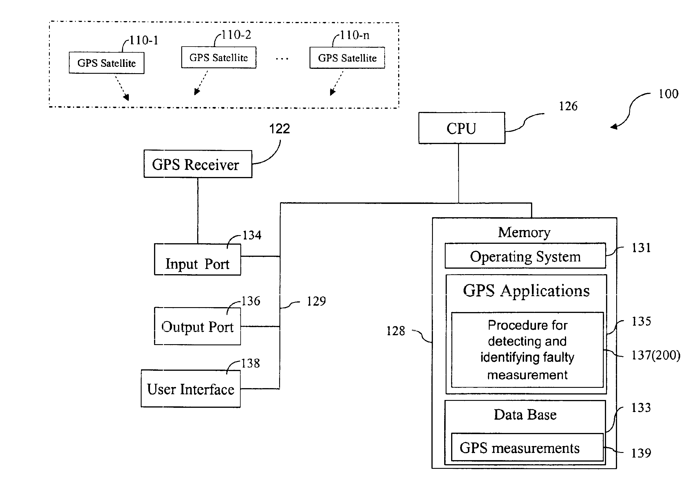
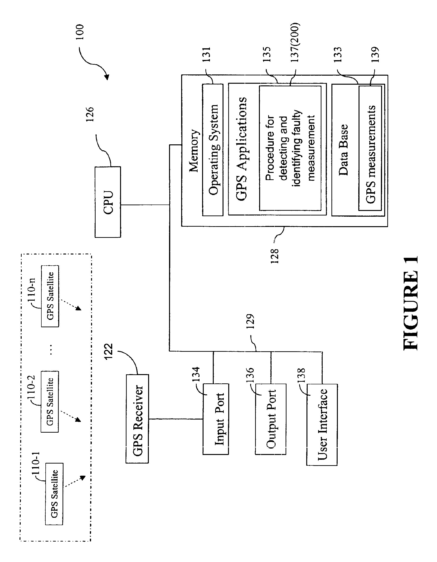
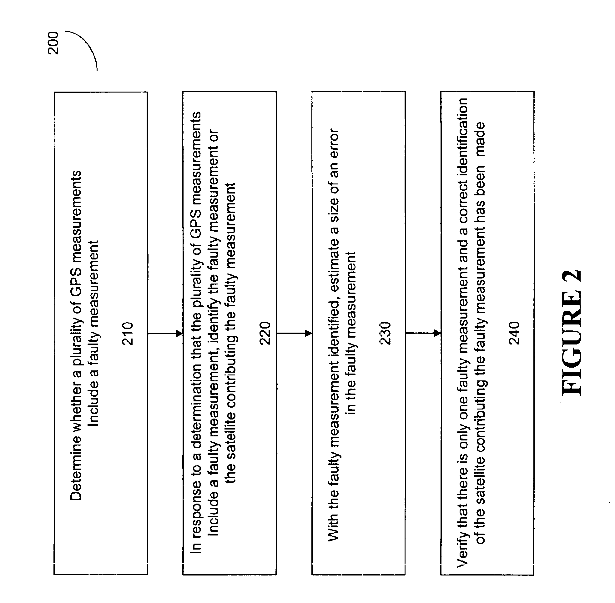
FIG. 1 illustrates a computer system 100 that can be used to carry out the method for detecting and identifying a faulty GPS measurement among a plurality of GPS measurements. Each of the plurality of GPS measurements is taken by a GPS receiver 122 based on signals from one of a plurality of satellites 110-1, 110-2, . . . , 110-n, where n is the number of satellites in view of the GPS receiver 122. The plurality of satellites, or any one or more of them, are sometimes referred to hereafter in this document as satellite(s) 110. In some embodiments, the GPS receiver 122 and the computer system 100 are integrated into a single device, within a single housing, such as a portable, handheld or even wearable position tracking device, or a vehicle-mounted or otherwise mobile positioning and / or navigation system. In other embodiments, the GPS receiver 122 and the computer system 100 are not integrated into a single device.

As shown in FIG. 1, the computer system 100 includes a central process...


PUM


Abstract

A method for detecting and identifying a faulty measurement among a plurality of GPS measurements, obtained by a GPS receiver with respect to a plurality of satellites in view of the GPS receiver, determines whether the plurality of GPS measurements include a faulty measurement. In response to a determination that the plurality of GPS measurements include a faulty measurement, the method identifies a satellite contributing the faulty measurement by computing a correlation value associated with each of the plurality of satellites, and selecting a satellite associated with a highest correlation value as the satellite contributing the faulty measurement.

Description

FIELD OF THE INVENTIONThe present invention relates generally to Fault Detection and Elimination (FDE) in a discrete-time controlled process, and particularly to methods for Receiver Autonomous Integrity Monitoring (RAIM) in global positioning systems (GPS).BACKGROUND OF THE INVENTIONGPS uses satellites in space to locate objects on earth. With GPS, signals from the satellites arrive at a GPS receiver and are used to determine the position of the GPS receiver. Currently, two types of GPS measurements corresponding to each correlator channel with a locked GPS satellite signal are available for civilian GPS receivers. The two types of GPS measurements are pseudorange, and integrated carrier phase for two carrier signals, L1 and L2, with frequencies of 1.5754 GHz and 1.2276 GHz, or wavelengths of 0.1903 m and 0.2442 m, respectively. The pseudorange measurement (or code measurement) is a basic GPS observable that all types of GPS receivers can make. It utilizes the C / A or P codes modula...

Claims


Application Information

Patent Timeline
Patent Type & Authority Patents(United States)
IPC IPC(8): G01S1/00G01S19/48G01S19/20
CPCG01S19/20
Inventor HATCH, RONALD R.SHARPE, RICHARD T.YANG, YUNCHUN
Owner DEERE & CO
Why Eureka
Try Eureka