
Stereoscopic display system for viewing without spectacles

a display system and spectacle technology, applied in the field of spectacle display system for viewing without spectacles, can solve the problems of difficult display devices of figs, unavoidable to feel unpleasant as foreign matter is put, and more agonizing to limit the position of the viewer's head than to wear spectacles

Inactive Publication Date: 2005-03-08
SONY CORP
View PDF7 Cites 27 Cited by
  • Summary
  • Abstract
  • Description
  • Claims
  • Application Information

AI Technical Summary

Benefits of technology

It is an object of the present invention to provide a display system for viewing without spectacles, capable of displaying a three-dimensional image by means of two-dimensional right- and left-eyed images with less crosstalk therebetween while avoiding the necessity to wear special spectacles and to provide an image separation mechanism in pixels, and at the same time, capable of attaining an increased degree of freedom in vertical movement of a viewer's head.
With the above arrangements, it becomes possible to attain a degree of freedom in the vertical movement of the viewer's head while separating the right- and left-eyed images to the right and left eyes precisely.

Problems solved by technology

In the method using special spectacles, however, it is unavoidable to feel unpleasant as if foreign matter is put on.
In the lenticular method and the parallax barrier method, there is a problem that the position of a viewer's head is limited owing to a stereoscopic radius of plus or minus few centimeters along a horizontal direction, so that it is more agonizing to limit the position of the viewer's head than to wear spectacles.
However, it is difficult for the display devices of FIGS. 9 to 11 to attain a degree of freedom in vertical movement of the viewer's head.
As a result, it is necessary to limit the position of the viewer's head.
As a result, the positional relationship between the image separation mechanism and the pixels becomes inappropriate, whereby crosstalk between the right- and left-eyed images occurs.

Method used


Image

  • Stereoscopic display system for viewing without spectacles
  • Stereoscopic display system for viewing without spectacles
  • Stereoscopic display system for viewing without spectacles

Examples


Embodiment Construction

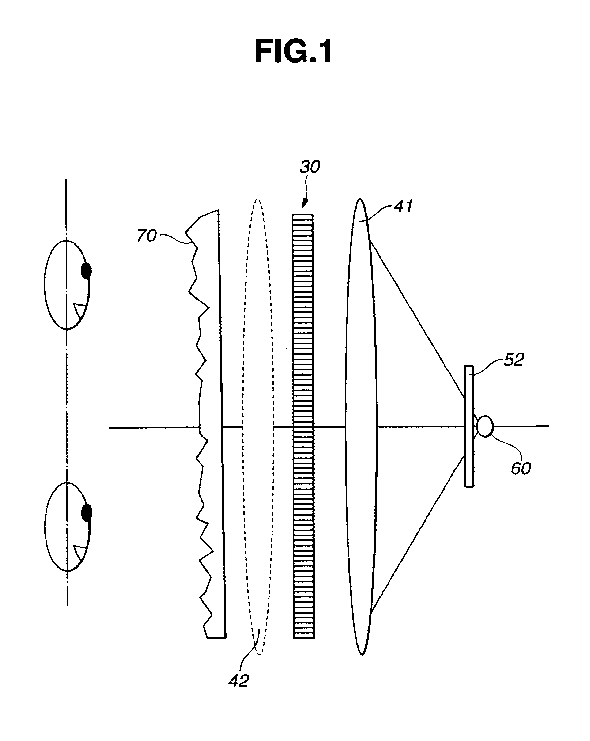
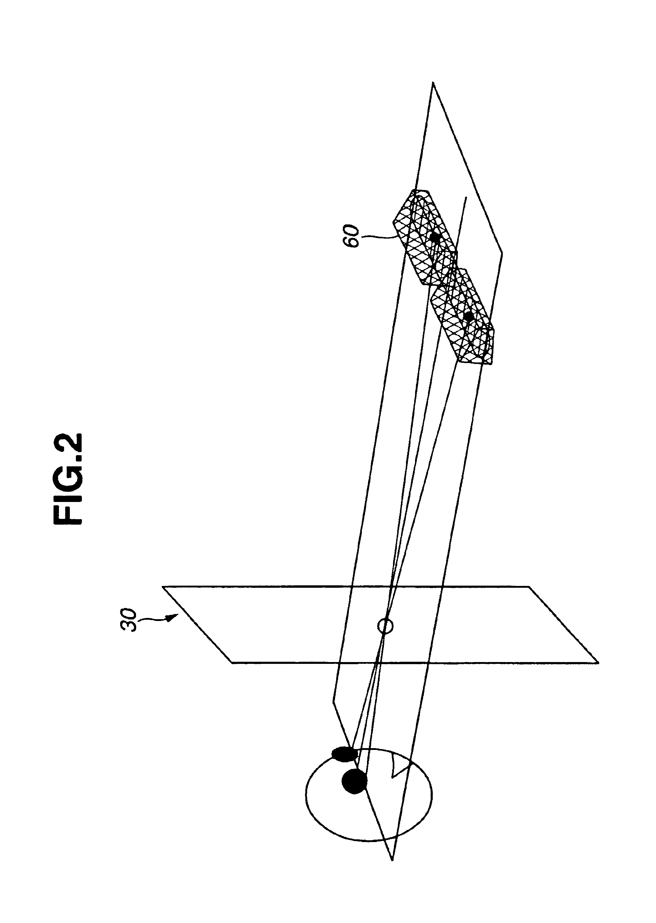
Hereinafter, embodiments of the present invention will be explained with reference to the drawings. Firstly, FIG. 1 is an illustration conceptually showing the structure of one embodiment according to the present invention. FIGS. 2 and 3 shows one detailed example of a backlight used in the present invention. FIGS. 4 and 6 shows specific examples of light diffusing means and their uses.

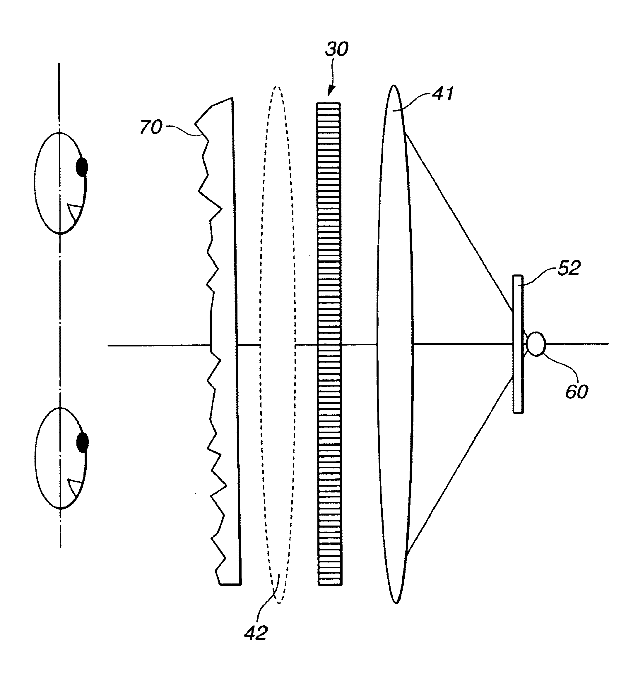
FIG. 1 is a vertical sectional view of a display system capable of displaying a right-eyed image (or a left-eyed image) in such a manner that the image can be viewed from vertically different positions of a viewer according to the invention. In FIG. 1, a reference numeral 30 indicates display means comprising a light transmission display, such as a liquid crystal display, provided with pixels (31) that form left- and right-eyed image areas and a first image separation mechanism (32) for polarizing the rays of light in different polarizing directions for left and right eyes.

A light sources 60 is provid...


PUM


Abstract

A light source (60) is provided in the rear of display means (30), which has a light transmission type display and is made up of pixels (31) for left and right eyes and a first image separation mechanism (32) for the left and right eyes, with a lens unit (41) having a collecting power in a vertical direction and a second image separation mechanism (52) therebetween. The transmission light from the light source (60) spreads in the vertical direction as shown in the drawing. Such spread of the light occurs over the whole of a display surface. It is therefore possible to view the image on the display surface, when the viewer's head is located at any of positions 1 to 4. Accordingly, it becomes possible to make a degree of freedom in vertical (up-and-down) positional movement of the viewer's head.

Description

BACKGROUND OF THE INVENTIONThe present invention relates to a display system for viewing without spectacles. More particularly, the present invention relates to a 3D display system for viewing without spectacles, capable of reproducing a three-dimensional image by means of two two-dimensional images having binocular parallax therebetween without the need for a viewer to wear special spectacles.BACKGROUND ARTA display device in general use at present gives a two-dimensional image, although a person ordinarily observes a three-dimensional image by virtue of binocular parallax in reality. It has been therefore required to develop a display device having the ability to display parallactic information.In order to reproduce a three-dimensional image by means of two two-dimensional images having binocular parallax therebetween, there have been proposed various methods in which separate images are projected onto left and right eyes, respectively. These methods include a method using special...

Claims


Application Information

Patent Timeline
IPC IPC(8): G02B27/26G02B27/22H04N13/00G02B30/27G02F1/13G02B30/25G09F9/00H04N13/04
CPCG02B27/2214G02B27/26H04N13/0404H04N13/0406H04N13/0497H04N13/0447H04N13/0481H04N13/0409H04N13/0418H04N13/0422H04N13/305H04N13/32H04N13/324H04N13/38H04N13/31H04N13/307H04N13/398H04N13/351G02B30/25G02B30/27
Inventor SATO, SEIJISEKIZAWA, HIDEHIKO
Owner SONY CORP
Learn More