Method of measuring wavelength dispersion amount and optical transmission system

a wavelength dispersion amount and wavelength technology, applied in the field of wavelength dispersion amount measurement and optical transmission system, can solve the problems of waveform distortion (pulse broadening), limiting transmission length, increasing costs, etc., and achieve the effect of high-quality transmission

Inactive Publication Date: 2005-03-08
FUJITSU LTD
View PDF4 Cites 18 Cited by
  • Summary
  • Abstract
  • Description
  • Claims
  • Application Information

AI Technical Summary

Benefits of technology

It is accordingly an object of the present invention to provide a method of measuring a wavelength dispersion amount of an optical transmission line, without disconnecting lines, and an optical transmission system which employs such a measuring method, performs dispersion compensation without either excess or deficit when switching optical transmission lines at an optical level, and realizes a high-quality transmission.
As a result, there is no longer a need for information on the wavelength dispersion amounts for each type of optical fiber, and future expansion of optical fiber types can be accommodated flexibly.
Thus, similarly to the method of the present invention, the measuring signal need not be returned, and application is possible even when the up line and down line between the nodes are asymmetrical.
That is, as described above, the dispersion compensation amount required is determined as a result of calculating the wavelength dispersion amount; hence by performing dispersion compensation at once for all wavelengths using a variable dispersion compensator (T-DC) positioned on the optical transmission line, dispersion compensation can be realized at a low cost.

Problems solved by technology

Because, as described above, the number of WDM wavelengths has increased to several hundreds of channels, it becomes necessary to prepare transponders (devices to perform optical / electrical conversion, reproduce a signal, perform conversion of a modulation format and a wavelength, and connect to another device) for the number of wavelengths at the transmission and reception nodes, thereby increasing costs.
Therefore, waveform distortion (pulse broadening) due to wavelength dispersion gives rise to intersymbol interference, and this in turn is a factor limiting transmission lengths.
However, in the cases of the optical add-drop method shown in FIG. 24B, and in the optical cross-connect method shown in FIG. 24C, it is anticipated that application of a technique like those described above will be difficult, for the following reasons:
This, however, limits the freedom of switching configurations; and because major changes in optical fiber characteristics due to path switching are conceivable, as for example when changing from single-mode fiber (SMF) to nonzero dispersion shifted fiber (NZDSF), it is difficult to adjust the wavelength dispersion amount of all paths to zero.
Further, it is unrealistic to attempt to measure wavelength dispersion amount in advance for all of a huge number of paths; and in cases where new paths are added, measurements for all the newly added paths must be performed once again.
In such cases there is a problem that lines in use must be temporarily interrupted.
Accordingly, in order to completely compensate for the wavelength dispersion amount, a design must also take into consideration the accumulated shifts in such wavelength dispersion amounts; however, it is extraordinarily difficult to perform complete dispersion compensation for all routes, while also taking wavelength dependency into account.
For the above reasons, there has been a problem that current methods for designing dispersion compensation amount cannot easily be applied to WDM optical transmission systems incorporating the functions of optical add-drop or optical cross-connect methods.

Method used


Image

  • Method of measuring wavelength dispersion amount and optical transmission system
  • Method of measuring wavelength dispersion amount and optical transmission system
  • Method of measuring wavelength dispersion amount and optical transmission system

Examples


Embodiment Construction

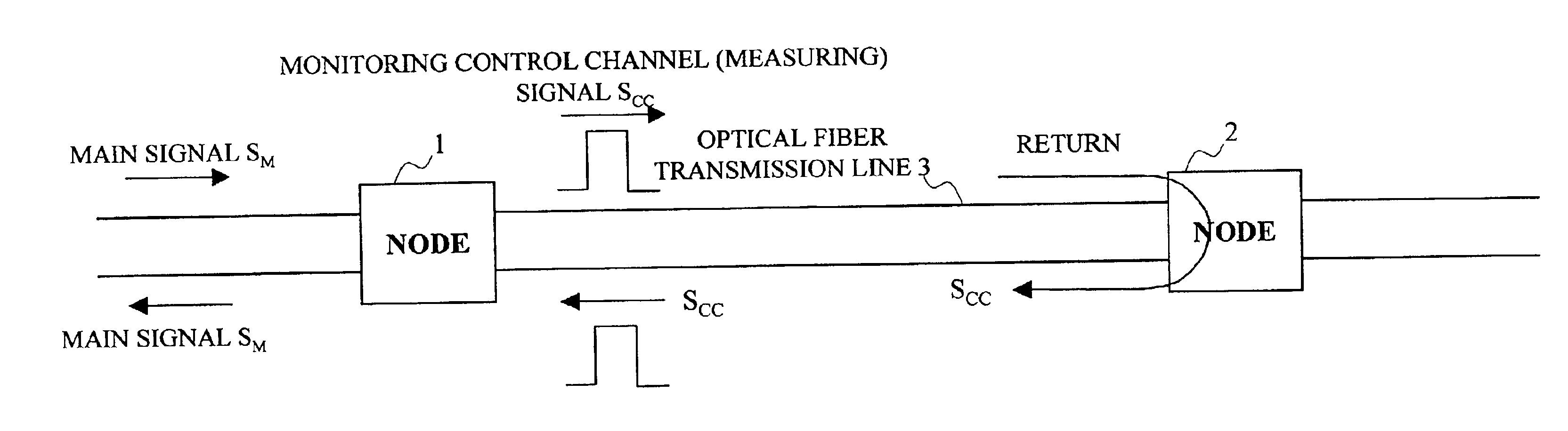
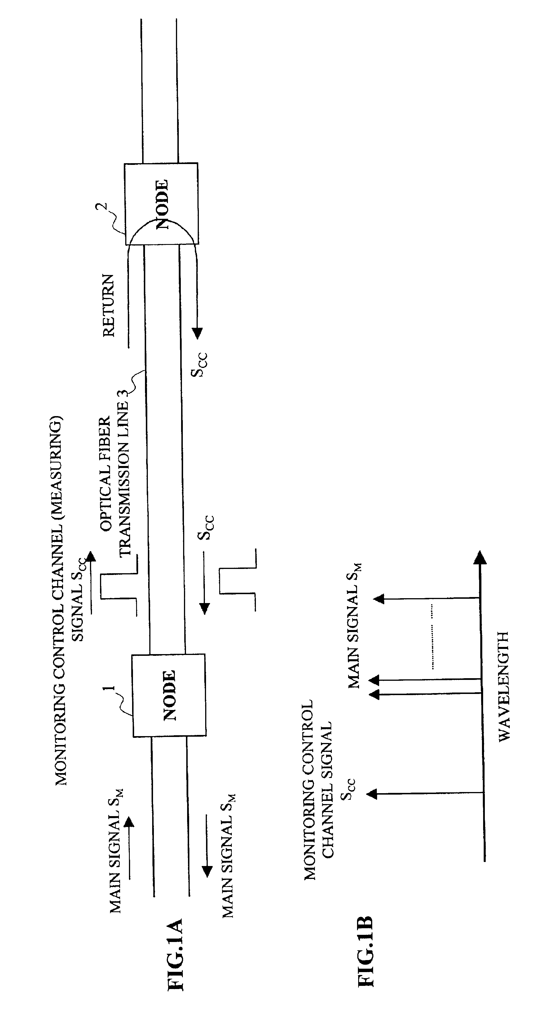
FIGS. 1A and 1B show an embodiment (1) of a method of measuring a wavelength dispersion amount and an optical transmission system according to the present invention. In this embodiment, nodes 1 and 2 composing an optical transmission system are connected with an optical fiber transmission line 3 composed of outgoing and incoming paths, where a main signal SM goes back-and-forth.

This system is configured such that a monitoring control channel signal Scc, that is the measuring signal, is transmitted from the transmission node, the node 1 (the first node), to the reception node, to the node 2 (opposing node), and is returned at the opposing node 2 to the node 1.

As shown in FIG. 1B, this monitoring control channel signal Scc is wavelength-division-multiplexed into the main signal SM.

At the node 1, a delay time T1 required for the return of the monitoring control channel signal Scc is measured, and from this delay time T1 a length L (km) of an optical fiber transmission line 3 is obtaine...


PUM

PropertyMeasurementUnit
wavelength dispersionaaaaaaaaaa
lengthaaaaaaaaaa
wavelengthaaaaaaaaaa

Abstract

Measuring a wavelength dispersion amount of an optical transmission line without disconnecting the optical transmission line. A measuring signal is transmitted together with a main signal from a first node while the optical transmission line is in operation. The measuring signal is extracted and returned at an opposing node. A delay time required for the measuring signal to return is measured. A length of optical transmission line between the nodes is calculated from the measured delay time. A wavelength dispersion amount of the optical transmission line is calculated based on the calculated length.

Description

BACKGROUND OF THE INVENTION1. Field of the InventionThe present invention relates to a method of measuring a wavelength dispersion amount and an optical transmission system, and in particular to a method of measuring a wavelength dispersion amount when wavelength-division multiplexing (WDM) signals are transmitted through optical transmission lines, and an optical transmission system using such a measuring method.2. Description of the Related ArtRapid growth of the Internet has been accompanied by corresponding rapid growth in demand for information transmission; a wavelength-division multiplexing (WDM) optical transmission system has been developed which combines from several tens to several hundreds of wavelengths into a single optical fiber for the transmission, and such a system is rapidly being deployed. At present, for the transmission rate per wavelength, 2.4 Gb / s is mainstream, which is hereafter expected to be replaced by a more rapid 10 Gb / s rate, and systems capable of 40...

Claims


Application Information

Patent Timeline
Patent Type & Authority Patents(United States)
IPC IPC(8): G01M11/00H04J14/02H04B10/08G01M11/02H04B10/035H04B10/07H04B10/071H04B10/077H04B10/2525H04J14/00
CPCG01M11/332G01M11/335G01M11/338H04B10/0775H04J14/02H04B2210/074H04J14/0201H04B2210/078H04B2210/071
Inventor MORI, SHOTAIZUMI, FUTOSHI
Owner FUJITSU LTD
Why Eureka
Try Eureka